|
How to work
out the minimum resistor value that can safely be used:
To
establish the minimum resistor value, Ohm's law can be used. This
relates the current through a resistor to the voltage across that
resistor and can be expressed as V/I=R with V=Voltage in Volts,
I=Current in Amps and R=Resistance in ohms.
The
maximum current is part of the LED specification. Let's use a figure
of 15mA (=0.015Amps) for this example, which would be safe for most
modern LEDs (including 0805 chip types.)
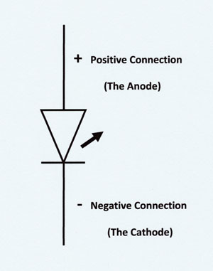
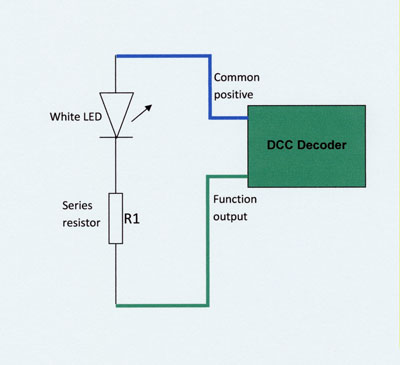
The
voltage across the resistor can be estimated as the decoder output
voltage minus the forward voltage drop across the LED when it is on.
The voltage at the output of most DCC decoders is approximately 14
Volts. The forward voltage drop across the LED can be found in the
specification. For a white LED this is approximately 3 Volts. So the
voltage across the resistor will be approximately 14 - 3 = 11 Volts.
So
using Ohms law, with a Current of 0.015 Amps and a voltage of 11
Volts, V/I=R, so R=11/0.015 = 733
ohms.
Moving to the next highest standard value of resistor, a value of
820 ohms or higher can safely be used.
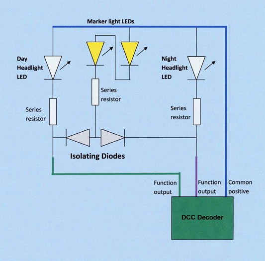
I
usually use around 2k7 for headlights, 10k for rear lights and
hazard lights and as much as 47k for directly viewed front marker
lights.
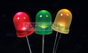
The
table below shows the forward current drawn by different colour LEDs
with some typical series resistor values when operating from a 14
Volt DCC output.
|
Colour |
Typical Application |
Single LED
Current |
2 Series
LEDs Current |
Series
Resistor Value |
|
White |
Very Bright
Head Light |
11 mA |
- |
1k |
|
White |
Normal Head
Light |
4 mA |
- |
2k7 |
|
Red |
Rear Light |
1.2 mA |
1 mA |
10k |
|
Warm White |
Front Marker
Light |
0.23 mA |
0.17 mA |
47k |
|
Amber |
DMU door
Warning Light |
1.2mA |
1 mA |
10k |
The best way to identify the optimum resistor value for a
specific application, is to equip yourself with a range of these
low cost components and to try a few values, homing in on the
effect you prefer.
|