| DCC conversion and Lighting update of the Hornby Class 142 Pacer twin car DMU. |
|
|
Introduction: This webpage provides a summary of the process adopted to incorporate DCC decoders and correctly operating external LED lighting in a Northern Rail variant of the Hornby 2-car Class 142 unit (OO gauge). Note that the smaller pictures can be enlarged by clicking on the image. |

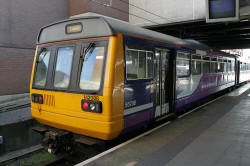
Class 142 in Newcastle Station
| DCC Conversion Approach: The plan is to use a 3 function and back emf motor controller TCS M3 decoder in the power car and a 4 function TCS FL4 (function only) decoder in the trailer car. To provide correct operation of the lights, 3 function outputs are required. External Lighting Modifications: The original Hornby model has no operational lighting. The real Class 142 units incorporate 2 light housings at each end. At the outer end of each housing is a rectangular warm white front marker light. At the inner end of the light housings are the circular red rear lights and in the centre of the left hand housings is the headlight. Although the right hand housings contain a circular lens and reflector at the centre, these lights are non-operational. Orange hazard lights are fitted on the roof line approximately mid way along each side of each car. It is planned to fit LEDs in all the operational light locations. The front and rear lights will be activated via controller button zero, with direction automatically assigned to the loco's direction of motion. The roof mounted hazard lights (which normally only come on when the train comes to a halt at a station platform) will be activated via controller button 1. |
| Circuit Diagram for
lighting and power car connections:
The resistors control the current flowing through each LED. This determines the intensity of the light generated by the LED. The values were established by experiment, for the LED types employed. Some adjustment may be required if different LED types are used. |
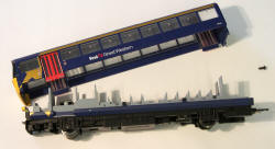
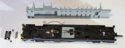
| Achieving Access to the
Power Car: First the upper body shell must be separated from the wheeled chassis unit. The screw in the rear door of the car must first be removed. Next the rear of the chassis unit and the rear of the upper body shell are gently eased apart. The front light housings form location "pegs" which attach the chassis unit to the upper body shell at the front of the unit. The chassis unit can be withdrawn from the upper body shell simply by pulling the two apart. |
 Unscrew and separate rear end first |
 Floor and seat insert with 8 pin socket and header |
| Removing the Hornby DCC
socket: After removing the 8 pin blanking plug, the original 8 pin DCC socket is removed from the floor unit by undoing the fixing screws. The leads are then de-soldered and extracted from the slots in the floor unit. The floor unit can then be separated from the chassis. The decoder and series resistors will be mounted under the floor moulding. |
 Undo the 2 screws to remove the 8 pin socket |
 After de-soldering the wires, the floor can be removed |
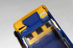
| Accommodating the LEDs: The construction of the light housings is useful in that wiring can largely be confined to the chassis unit, but challenging in that care is needed not to compromise the structural integrity of the front of the unit. The rear light and headlight holes are drilled out from the front. 2mm tower LEDs are inserted from the rear. The marker light apertures (for 0603 size chip LEDs) are drilled and filed to shape from the front. Holes for the chip LED leads are drilled at each end of the rectangular aperture from the front. The non-operational right hand headlights are left as painted discs. The tower LEDs should be a tight fit and when the common positive terminals are wired together, the assembly is robust enough to stay in place. The marker light 0603 chip LEDs are glued in place using cyanoacrylate adhesive (super glue). |
| Eliminating "Light bleed"
between the new LEDs: Light from the tower LEDs will couple into adjacent devices if fitted straight out of the bag, producing a very unrealistic effect. To prevent this, the LEDs are painted with gloss black modelling enamel, leaving just the outer face of the 2mm diameter tower exposed. I now also paint a white dot on the negative side of the LED body (shortest lead) before use, to avoid later wiring errors. Once the LED leads are trimmed, its easy to forget the polarity! |
 Light housings before drilling
|
 Holes drilled and filed
|
 LEDs inserted
|
|
| Floor/seating insert modifications to
fit the LEDs: The body and leads of the 2mm tower type LEDs protrude at the rear of the light housings. To accommodate this, plastic has to be removed from the front of the floor/seating insert moulding. Also, the underside of the shelf at the base of the front windows in the upper body shell requires material to be removed in order to accommodate the top of the rear bodies of the tower LEDs. The plastic can be melted with a soldering iron, with care taken not to penetrate through to the top of the shelf. Finally, a tunnel is cut in the base of the cab section of the floor/seating insert, to route the LED wiring under the cab. Additionally, it was found necessary to reduce the width of the cab rear wall, to enable the chassis unit to be joined to the upper body shell with the floor/seating moulding in place on the chassis. (not shown on the image below). |
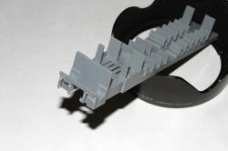 Modified Floor/Seating moulding |
 Upper body shell modifications |
| Adding current control resistors: The resistors and the M3 decoder (as shown in the circuit diagram above) are mounted in the narrow under-floor space. The motor and wheel pick-up wires are soldered to the corresponding decoder wires, with the joints insulated using heat shrink sleeving. |
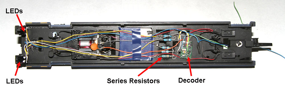
M3 Decoder and series resistors mounted under the floor/seating insert (resistors are super glued to the chassis floor)
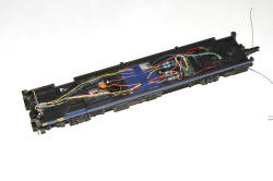 The wired chassis |
 With the floor/seating moulding added |
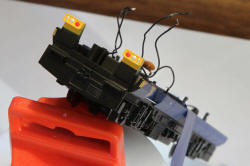
| Fitting the
hazard lights: The roof mounted hazard lights only illuminate when the train is stopped and the doors are open or enabled in normal operation. However, several safety systems (including track circuit actuator fault and automatic fire warnings) can also trigger the lights to activate. Rail staff are advised to phone in details to the duty signal box if they ever spot a train moving with the hazard lights on! The model hazard lights are orange 0603 size SMD LEDs. These are super-glued in place on the roof of the upper body shell. The wires to these LEDs are routed through holes pre-drilled in the roof, and then taken to the rear of the car, within the roof section. The wires are then routed down the rear corner of the car, leaving several centimetres of wire to be connected to the chassis unit. Holes are made in the glazing moulding roof directly below the LED locations. The LED wires and the thicker wires to the rear of the car are both routed through appropriate holes. The wires are soldered together as indicated in the circuit diagram (using sheets of paper to protect the inside of the windows from solder fumes). The wires are then pulled up into the roof section, out of sight.
The series resistor is mounted adjacent to the decoder in the chassis. Wires from the series resistor and the common decoder positive are routed out through the hole in the rear floor of the chassis, ready to be connected with the corresponding two wires in the roof section, when the upper body and chassis are re-united. When the upper body shell is fitted to the chassis unit, the two wires from the LEDs are fed through a hole in the floor of the chassis before the rear of the upper and lower body are brought together. After the rear screw is refitted, the unit is inverted and the two pairs of wires are soldered together and insulated with sleeving. The wiring is then concealed by clamping to the underside of the car with black painted Blu Tack. |
| Programming the CVs: Using the DCC controller (mine is a Bachmann Dynamis) the CV values are programmed into the decoder.
The same DCC address should also be programmed into each decoder |
||||||||||||||||||||||||||||||||||||||||||||||||||||||||||||||||||||
| Testing the Lights: Button 0 should activate the left hand headlight and both marker lights in the forward direction for this car and both rear lights in reverse). Button 1 should activate the hazard lights (in either the forward direction or reverse direction). (The direction of motion was found to be opposite to that expected, so the decoder orange and grey wire connections were reversed.) Programme the DCC address into the car. |
|
Front lights are OK (button 0, forward) |
Rear lights are OK (button 0, reverse) |
Hazard lights work OK (button 1) |
| Modification of the
trailer
car: The trailer car lighting modifications are carried out exactly as described above for the power car, except that there is no 8 pin socket to be removed and no motor connections to be made. The FL4 decoder brown and pink wires are used in place of the M3 decoder white and yellow wires.... as indicated in the circuit diagram. When the modifications are complete and the trailer car has been successfully tested, it is time to connect the two cars together via the twin conductor coupler. |
| Testing the two cars
together: Both cars have been programmed with the same address. So both cars should respond to the lighting control buttons in the correct manner. Test the cars as a complete train and confirm all is well. |
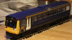
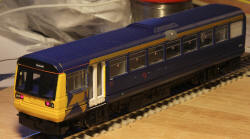
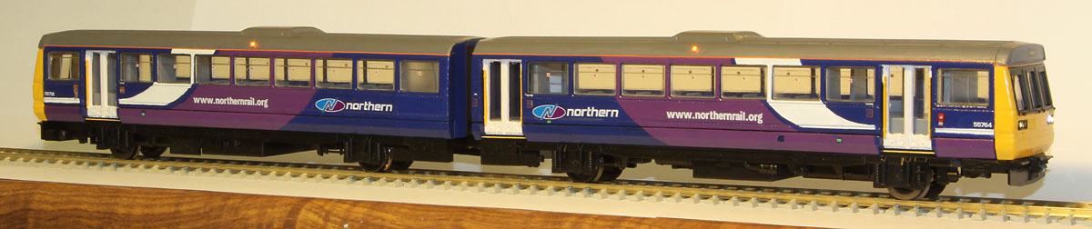
| Cosmetic Modifications: The Hornby model that formed my starting point is a First Great Western operated unit, with body colours from previous First North Western service. To convert it to current Northern Rail livery, a painting operation is required, followed by the application of Northern Rail water slide decals, obtained from Precision Labels & Decals. The door shape of the Hornby model has been superseded by 2 section doors on the real Pacer units. The 2 redundant vertical bars are therefore removed from the Hornby model, using a sharp craft knife and the remaining door frame is painted white, with yellow grab rails, to reflect Northern Rail practice. The blue roof is painted grey, using Humbrol 164 satin enamel. The yellow painted area at the front, is extended as indicated on the photo of the Northern Rail Pacer unit at the top of this page, using Humbrol 69 gloss enamel. The sides are painted in Northern Rail blue, white and purple colours. The NR blue is Revell "blue" gloss enamel 51. The NR purple is a mix of Humbrol 68 "Purple" gloss enamel and Humbrol 22 "white" gloss enamel. The straight line interfaces are masked with Tamiya masking tape and the curved interfaces are painted by eye (with a few inevitable subsequent adjustments). Orange cant rail waterslide decals (from Fox) are fitted between roof and sides, then Northern Rail waterslide Decals (from Precision Labels and Decals) are applied. NB: DO NOT use a brush coat of Humbrol Satincote over Precision Labels & Decals transfers...... I just destroyed the decals on one side of one car using this approach! ...But I should have read the instructions first. Precision Labels & Decals advise that due to the fragile nature of this type of decal, air brush varnish application is recommended, using several thin coats. Thankfully the Fox cant rail decals (which use a different form of carrier film) were fine. Fortunately I have enough spare decals to redo the affected area. Finally a pair of dummy BSI couplers are fabricated from plasticard and fitted over the two dimensional facsimiles on the chassis fronts. |

Hornby Class 142 pair in Northern Rail livery
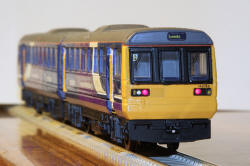 Model Class 142 |
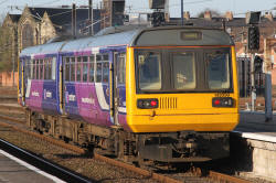 Real 142 pair departing York Station for Leeds |
| Final Tweaks: A little yellow water colour paint was applied to the white marker lights to give a "warm white" glow. The intensity of the hazard lights was also reduced by changing CV51 from 32 to 44 and by the application of a little orange water colour paint to the LED lenses. |
Hazard lights switched on
| Supplier website links:
The photos of real class 142s were taken at Leeds, York and Newcastle in 2009. The photos of the model were taken on the kitchen worktop using a tripod at 200 ISO. |