| A second DCC conversion and Lighting update of the Hornby Class 142 Pacer twin car DMU, this time, including sound and internal lights. |
|
|
Introduction: This conversion uses the Hornby Northern Rail liveried "Pacer" as a starting point. The story begins with the planning stage. Then the real work begins.... and the original plans may have to go out of the window. There isn't a lot of room in the Pacer to hide decoders, capacitors and speakers, so it will be a bit of a challenge to conceal the extra parts...... Note that the smaller pictures can be enlarged by clicking on the image. |
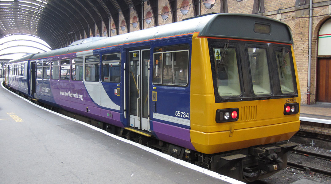
Class 142 in York Station (with rear lights on)
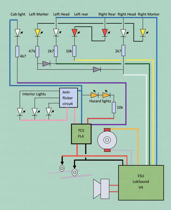
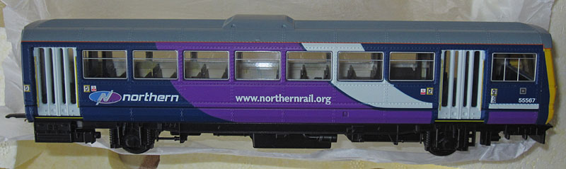
| DCC Conversion Approach: The plan is to use an ESU LokSound V4 decoder plus TCS FL4 (function only) decoder in the power car and a 6 function ESU LokPilot FX (function only) decoder in the trailer car. To operate the lights, 6 function outputs are required in the power car and 5 in the trailer car (no cab light fitted there). External Lighting Modifications: The original Hornby model has no operational lighting. The real Class 142 units incorporate 2 light housings at each end. At the outer end of each housing is a rectangular warm white front marker light. At the inner end of the light housings are the circular red rear lights and in the centre is the headlight. (Early in 2012, Northern Rail updated the 142s to include day headlights on the right hand side and Night headlights on the left hand side.....So my original Pacer also needs some modifications to incorporate the changes...... Amber hazard lights are fitted on the roof line approximately mid way along each side of each car. (These normally come on when the doors are open during a station stop.) Internal Lighting Modifications: Pure white LEDs will be used here: One in the driver's cab and three to illuminate each car's passenger compartment. Cosmetic Changes: The extra vertical parts in the doors will be removed. The sides of the yellow areas at the end of each car will be brought into line with the real units as shown in the photos. The light housings will be painted black. The 2 dimensional BSI couplers will be made 3 dimensional. A driver and a few passengers will be fitted. Internal toilet partitions will be added, within the rear of the cars to hide the electronics. |
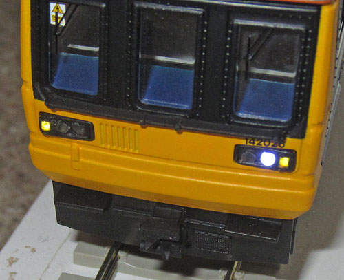
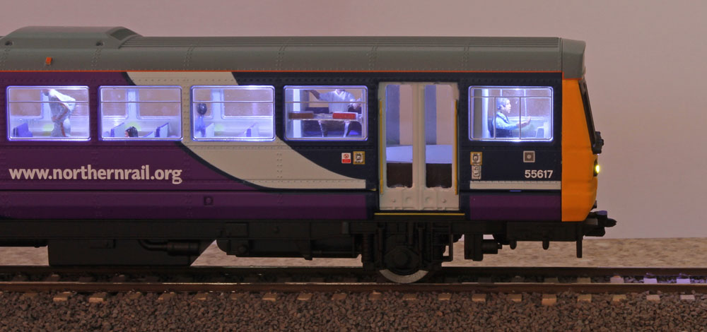
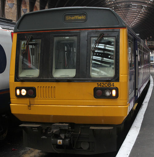 Showing the front daylight running lights on (For night running, the headlight below the unit's number is used instead)
|
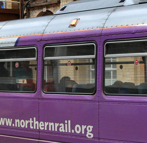
 Showing the side of the yellow painted area at the front of the car and the 2 piece doors. Both of these need cosmetic modifications to the original Hornby model The rail below the windscreens also needs to be painted black. |
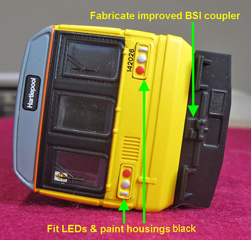 |

Showing the mods required |
| Proposed Circuit Diagram for
the power car:
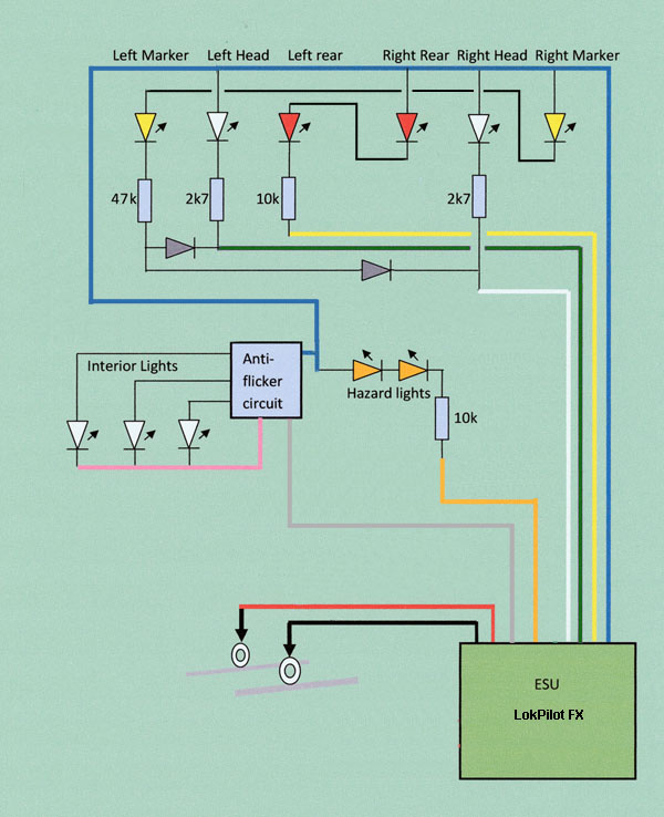
Proposed Circuit Diagram for the trailer car:
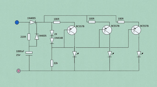
Proposed Anti-Flicker Circuit Diagram
|
First look inside the new Hornby Northern Rail 142:
And initial thoughts on where the electronics will fit......
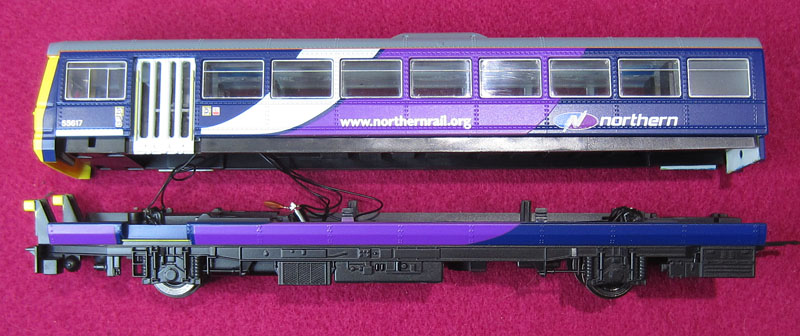
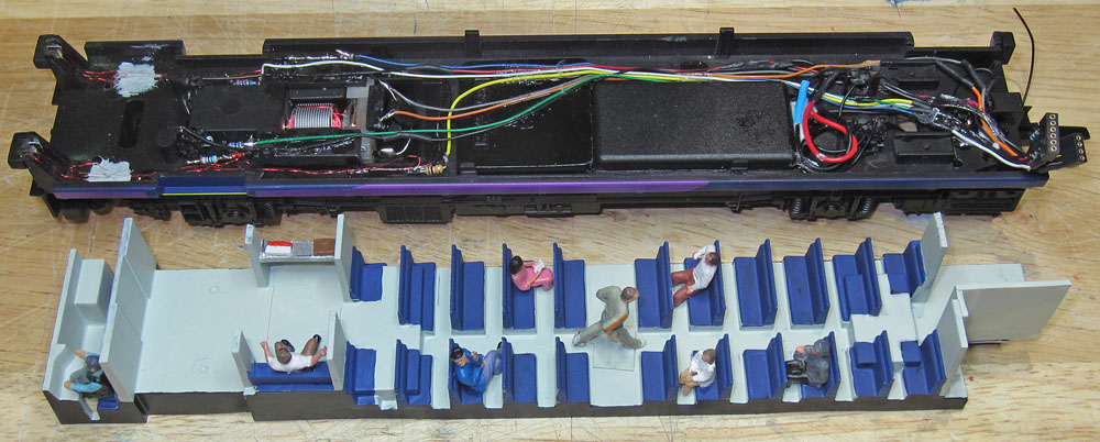
Hornby 142 power car dismantled for the first time......a timely reminder that I need to associate
the seating insert with the upper body shell for re-assembly and NOT with the chassis
The chassis with the tiny motor
Those black seats and internal flooring will need painting to match Northern Rail colours!
Great! Hornby have moved to a more open glazing system and they've painted the inside of the roof white!
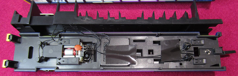
Its becoming apparent that the only space that I can hide the LokSound V4 is in the rear roof underside! The FL4 & anti-flicker
parts will also go in the roof, under the central bulge. A toilet box opposite the rear door will hide a cable duct and the
anti-flicker capacitor.
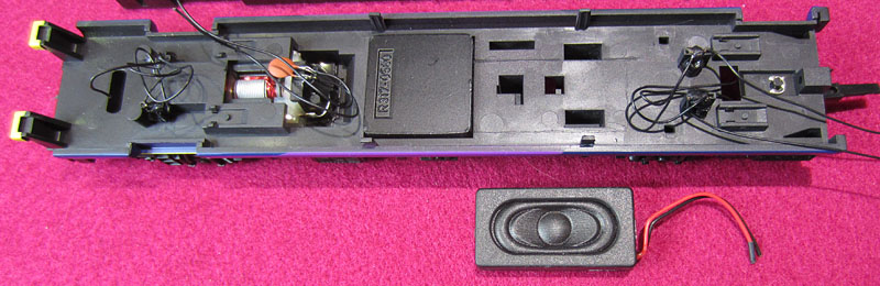
Can't quite get my favourite ESU 50334 to fit, so its a DCC Supplies 20x40 sealed enclosure instead
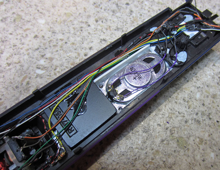
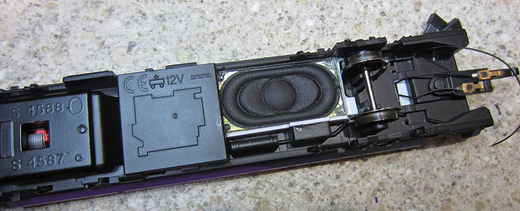
Half an hour of hacking results in a 20x40mm hole in the chassis floor to accommodate the speaker
(I'll refit some of the underside bits within the speaker hole area, to the speaker box later on)
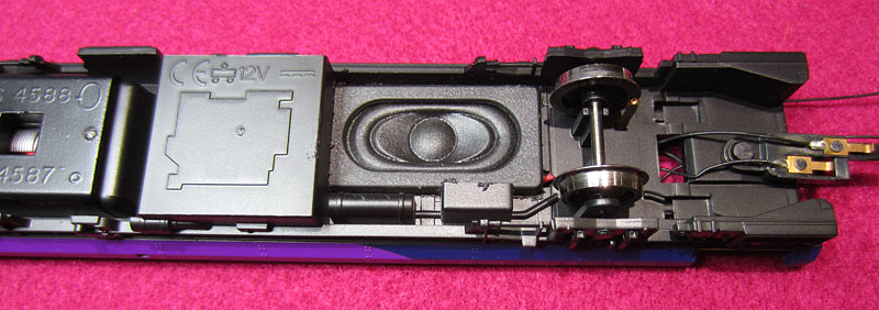
The speaker is mounted semi-recessed with the back just touching the bottom of the seating insert.
The LED series resistors will go under the front porch floor. All wiring will route rearwards to terminate
below the new (floorless) toilet enclosure, where multi-way miniature connectors will interface with the decoders.
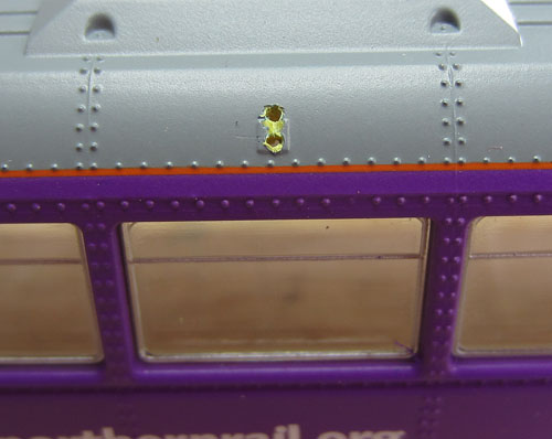
| Sorting out the External
lights: 1.5mm diameter holes were drilled through the painted headlights and rear lights on the power car light housings. A 0.8mm drill was used to open up (near) rectangular apertures corresponding to the forward marker lights. (With a hole penetrating through the aperture rear wall for the wires to pass through.
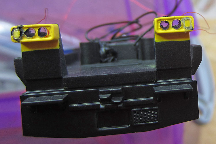
Holes drilled and marker light LEDs glued in place. When the glue is dry, the plastics will be tidied up & painted black.
"prototype white" pre-wired chip LED "Nanolights" were then glued in place to form working front marker lights. The collateral damage created when making the holes was then made good and the light housings received a coat of satin finish black paint. Short lengths of 1.5mm clear plastic light pipe were cut and filed to provide flat surfaces at each end. The light pipes were then placed in the holes, with the front surface flush. Daylight white and signal red Nanolights were then glued to the rear surface of the light pipes, and also secured to the rear of the light housing plastics.
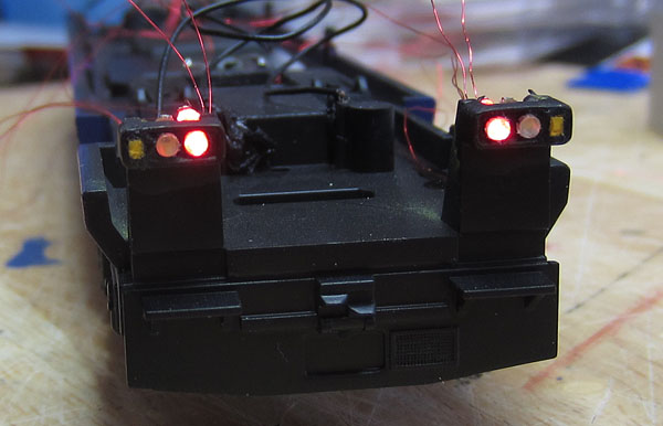
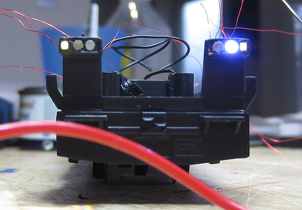
Rear lights fired up for the first time (using a bench PSU). Note the red leakage into the adjacent headlights.
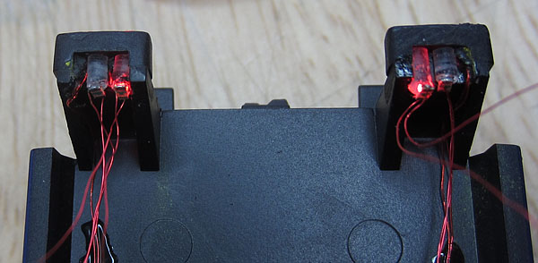
Showing the light housings and LEDs from above (rear lights still on).
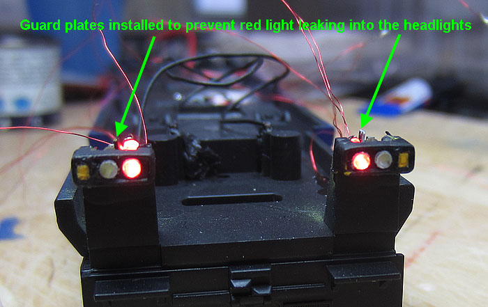
Thin black painted plasticard guard plates are required between the rear ends of the light pipes to prevent light leaking into the adjacent pipe.
Light leakage fixed!
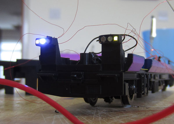
Forward day running lights
Forward night running lights
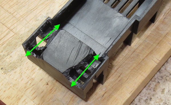
Wires are routed down the rear of the light housing supports to the chassis floor and glued in place below the channels cut in the seating moulding for this purpose:
Channels cut in the underside of the seating moulding to allow the lights wiring to pass along the top of the chassis
Series resistors, diodes and wiring (in line with the circuit diagram) all glued in place |
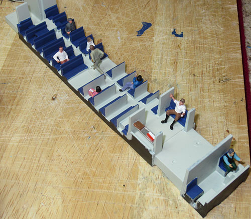
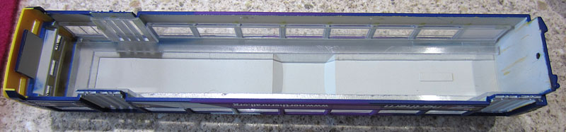
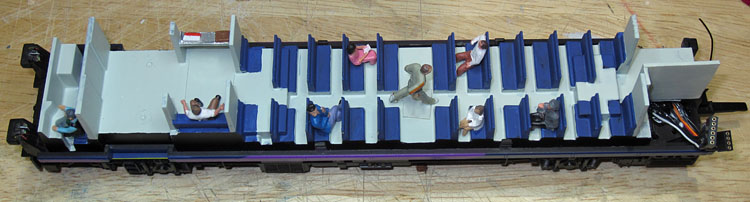
| Some cosmetic work on the
seat moulding: Further plastic was removed from the underside of the seat moulding to clear the wiring below, until it could be properly seated on the chassis. A thin plasticard sheet was glued over the slots above the motor & additional side facing seats and a luggage rack were fabricated for this area. The top side of the moulding was painted pale grey overall. The seats were then painted matt dark blue and a driver plus a few passengers were glued in place.
|
| Power Car Interconnections
between chassis and upper body assemblies: Multi-way miniature connectors are used to connect the LokSound V4 and TCS FL4 decoders to the chassis wiring. The diagram below shows the planned arrangement:
|
Connectors wired into the chassis assembly
.....and the seat moulding still fits OK!
| Moving on to the
Power Car Upper Body: First the hazard warning lights:
Next modifying the old four piece doors to become the newer two piece doors:
"Before"....... The trailer car showing the original 4 piece doors
"After"........Unwanted verticals removed with a Stanley knife. Just needs a bit of smoothing and a drop of white paint
Where will the decoders and upper body parts and lighting fit?:
Looking up into the roof of the upper body.....a rough plan of the proposed component locations The big ESU LokSound V4 decoder fits in the roof at the rear of the car. The TCS FL4 function decoder is glued inside the central raised roof area. Three LEDs beam downwards to illuminate the passenger seating areas and the flicker-free circuit powering these is distributed across the roof, with a capacitor inside the toilet. The cab light beams down into the driver's zone. The interconnections with the chassis, fit beside the capacitor inside the screened off toilet area.
Not quite as tidy as the diagram, but wiring is in progress...... |
||||||||
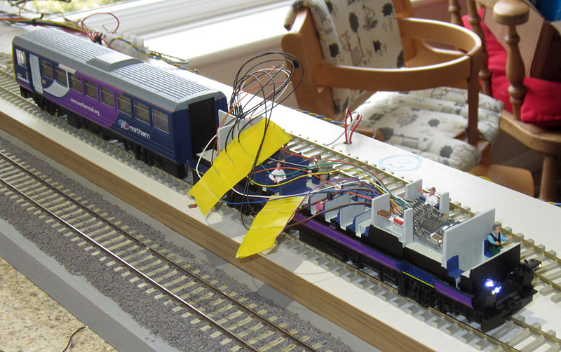
| Initial Test of the
LokSound V4 Decoder: Now is a good time to try out the LokSound decoder. I don't want to have to extract it from its location in the roof once its fixed in place.... so I need to verify that its working OK first.
Power Car chassis hooked up to the trailer car to provide more reliable rail contact Serious Motor Control Problem: The first revelation was an unstable BEMF control loop. With the original Howes values, the loco wobbled on the first speed step & went off like a rocket on the second step. It then came back under control at approx 1/4 speed. I expected a few issues with the very small Hornby 142 motor, which must have a very low inertia, but I've never come across behaviour quite like this! After carefully ploughing through a structured sequence of adjustments of the Motor control CV variables, I eventually got it under control and behaving across the speed range. There may be other combinations that achieve this result, but the CVs I ended up with are as follows: (Motor control CVs are in the orange cells of the table below.)
Unimpressive Speaker performance: The next issue was the sound quality..... With the DCC Supplies 20x40mm enclosure speaker, the results are disappointing. I'm going to look again at the possibility of using a replacement unsealed ESU 20x40 type 50334 speaker. I've used this speaker successfully on several other locos, so hopefully it will add a bit of quality here. The speaker has to be mounted a little below the chassis floor level to keep the rear of the magnet clear of the seat moulding. I've sealed the speaker to the chassis underside and I hope the upper body will give enough isolation between the sound pressure waves from the front and the back of the speaker.
Where there's a will, there's a way! Now, when the glue/sealant around the periphery of the speaker sets, I'll give it a try .......... Significantly louder and a bit more bass. I'll have to wait til I can get the upper body refitted for the full effect, but its certainly an improvement. |
| Decoder
Programming:
It all fits back together again OK! 1) LokSound V4 with Howes Sound Files: A few changes to get the function buttons in the right order for a station stop and to free up buttons in the 0-12 range for the FL4 & LokPilot FX controlled lights:
Detailed CV change action:
A few tweaks to the sound levels:
2) TCS FL4
3) Trailer Car LokPilot FX
|
Next, the trailer car!

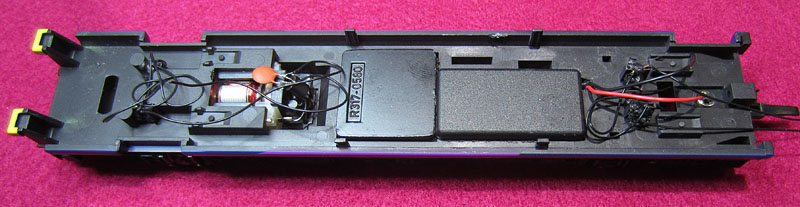
The function decoder fits in the empty motor housing, leaving just 3 wires to feed the internal lighting and hazard warning lights in the upper body.
| Trailer Car Problems: 1) With the trailer car re-assembled, the lighting all works as planned...... except that the rear lights are on the bright side and there is some light leakage between the adjacent headlights and rear lights. I'm going to try using black paint, applied to the side of the light-pipe formed by the rear light lens. Just in the area near the LEDs, where the two light-pipes run close together. I expect the paint to reduce the light level through the rear light lens, but this would actually be beneficial. ..........Success! Light pollution problem solved ..... and as expected, a slight drop in light level from the rear lights. 2) The capacitor and connector hidden in the toilet compartment can be seen through the frosting of the window. 0.25mm white plasticard immediately behind the window solves that problem! 3) A few flecks of dust were left on the inside of the windows.... these will be removed before final re-assembly.
Final Trailer Car Completion: 1) The modified doors need careful painting to avoid white paint getting on to the door glazing. Paper slid between the frame and the glazing, while the paint job is done, provides a fix! 2) The rear dividing line between the yellow warning area and the side blue is corrected. Also, the rail below the windscreens is painted black.... Both in line with the photographic evidence. 3) A more realistic (dummy) BSI coupler is made from layers of plasticard, painted black and fitted in place of Hornby's moulded attempt on the chassis end-plate. These final updates are also applied to the power car, which also receives black paint on the visible speaker surround. |

Day running lights on
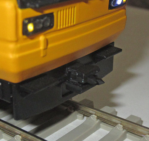 |
 New BSI coupler fabricated from layers of plasticard. |
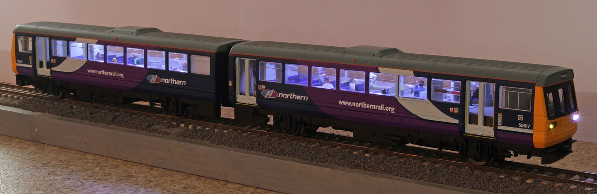
Night running lights & passenger compartment lights on.
Driver's cab light on (normally switched off when the train is under way)
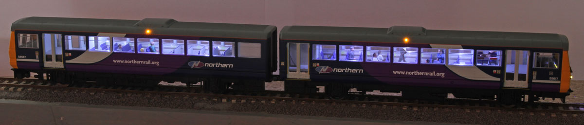
Simulated night station stop, with hazard lights on

No peace for the Pacers........Off to Hartlepool again!
Now you've read the webpage........Check out the film! Click Here for Youtube Video
| Supplier website links:
The photos of real class 142s were taken at York in 2012. The photos of the model were taken on the kitchen worktop using a Canon Ixus & DSLR. |