|
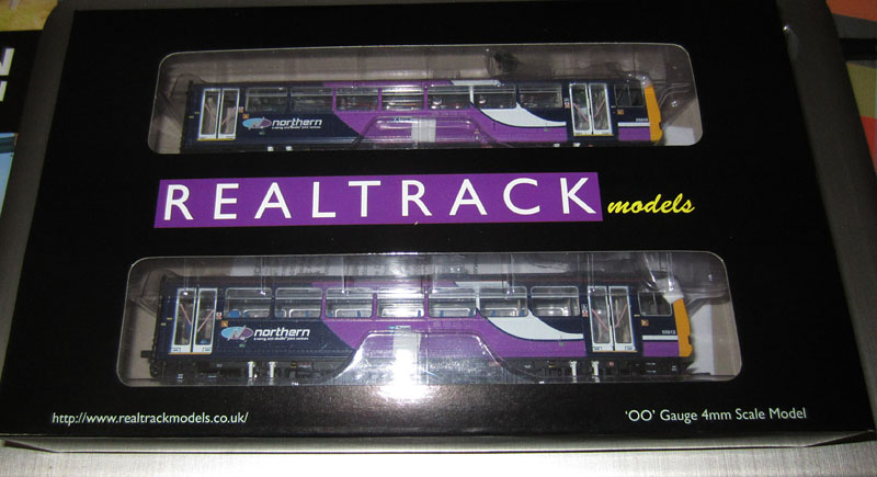
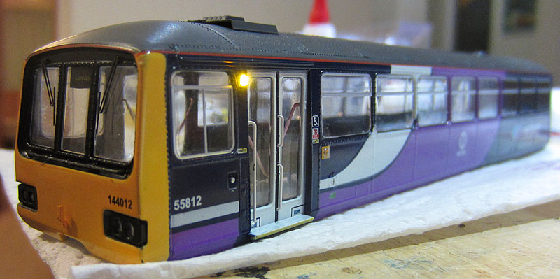
A DCC conversion and Lighting update of the
Realtrack Class 144 twin car DMU, including
night headlight, door hazard lights plus a sound system.
|
|
|
Introduction: This conversion uses the Realtrack Northern Rail liveried Class 144 as a starting point. The Class 144 model is an excellent 1/76 scale representation of the real locomotives. However there are of course a few updates that can usefully be applied. I've ended up with two of these units and this web page summarises my views on aspects of the model that can be improved and shows how the modifications have been (or will be) implemented. The original blog style account was looking increasingly disjointed, so here is (I hope) a better summary.......
|
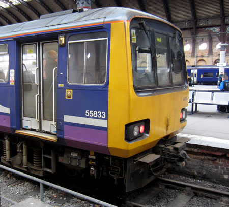
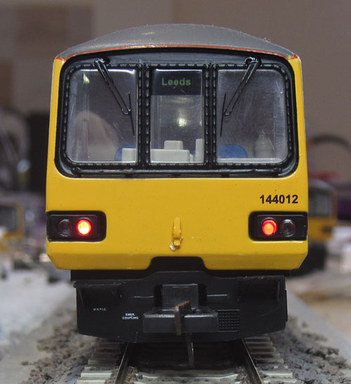
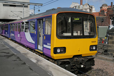
Pristine Class 144 off duty in Leeds Station
| Scope of the
improvements to be carried out: I've ended up with 2 sets of these splendid DMUs. One power car works rather better than the other on analogue DC, so I'll modify the better unit first. Damaged springs in the suspension maybe at least one reason for the performance difference: The best unit had only one out of four badly assembled and hence damaged spring, whereas the poorer performer had 3 out of 4 damaged. (All now repaired and I have a new assembly technique that should prevent a recurrence of the problem: see section 4 of the update details below.) Apart from this, its a neat little model, but as usual, there is scope for some enhancements.............. 1) External Lighting: Running lights: The model includes daytime running lights, which use the right hand headlight and left hand marker light at the front of the train and twin rear lights at the back. However, colour and intensity are a problem. And of course, the night running lights need to be added. The new running lights are directional and controlled via DCC. An additional lighting combination, seen on the real trains when waiting in the bay platforms of York station, is rear lights on at both ends of the train. This can also be selected via the DCC controller.
This unit at York station, has rear lights active in both cars, while awaiting its return run to Hull in a bay platform.
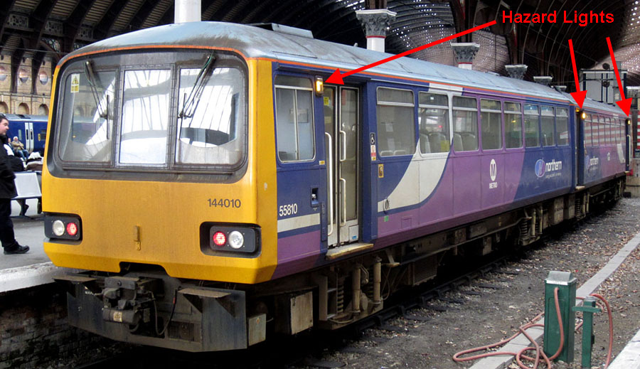
Hazard Lights: These are situated just below the roof line beside each passenger door. Each car has 3 of these amber coloured lights.
A rather weathered 144 in York station. The "hazard" lights normally only illuminate when the doors are open. (On the far side of this unit.)
Amber LEDs under DCC control will be fitted in place of the original painted mouldings. These can be synchronised with the door opening and closing sounds available on the decoder.
2. Internal Passenger compartment lighting: The original light pipe based system is very dim. This will be replaced with 3 white LEDs per car, powered under DCC control via an anti-flicker circuit. The roof underside will also be painted white, to reflect ambient light back into the car.
3. Decoders and Sound System: An ESU LokSound V4 decoder equipped with a Howes 142 Sound Project, will be installed in the trailer car, together with a 40x20mm ESU 50334 speaker. An additional TCS FL4 function decoder is to be fitted in the power car to provide the required lighting control options. It was a difficult decision between Bif's 144 and Bryan's 142. I expect Bif's sounds to be spot on for accuracy and I really rate his big diesels e.g. Class 60, but I have found his DMUs (e.g. Class 158 & Voyager) to lack punch when the engine volume should increase dramatically from idle level, as the loco winds up during a station departure. Even though Bryan's (Howes) sound project is for the Class 142 (albeit with the same engine and transmission as a 144).... I do like his approach to that crucial engine wind up, even if (as Charlie points out) the door warning tones on the 144 are somewhat different from those on the 142. I hope we soon see a 144 departure sequence on Youtube with Biff's sound system on board! I would be very happy to find my concerns about the likely engine volume-level ramp-up from idle, when the engine revs up for departure, are misplaced.
4. Wheel box suspension spring fitting: When the first power car was first dismantled, I discovered that 3 out of the 4 suspension springs had not been fitted correctly and consequently were damaged and not allowing the suspension system to work. (Also 1 out of 4 in the 2nd power car.) I was able to bend the damaged springs sufficiently back into shape to repair the fault, but only by making some modifications to the metal seat base casting, to assist with spring alignment during re-assembly. All cars have now received this modification.
5. Adding a driver and some passengers: I still have a number of Noch HO scale seated figures in the spares box, which will be used to populate the train. |
|
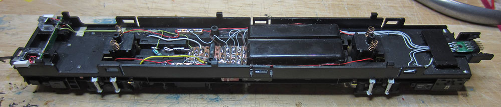
Getting Inside the
Power Car:
6 clips hold the upper body shell in place. Easing the upper body sides outwards enables the top to be unclipped and removed.
Removing the passenger compartment roof lighting:
The roof light pipe is clipped at the front but glued at the back, so it was removed together with the rear internal bulkhead wall.
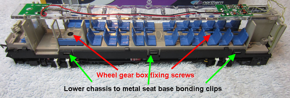
Separating the cast metal seat base moulding from the chassis:
Two screws hold the wheel gear boxes to the metal seat base assembly. These are first unscrewed. 6 clips hold the chassis sides to the metal seat base. These are gently unclipped starting at the rear and the lower chassis is flexed away from the metal seat base. |
| Inside the
Trailer Car:
Its a lot easier now I know where those clips are, but I still managed to displace the headlight light pipe!
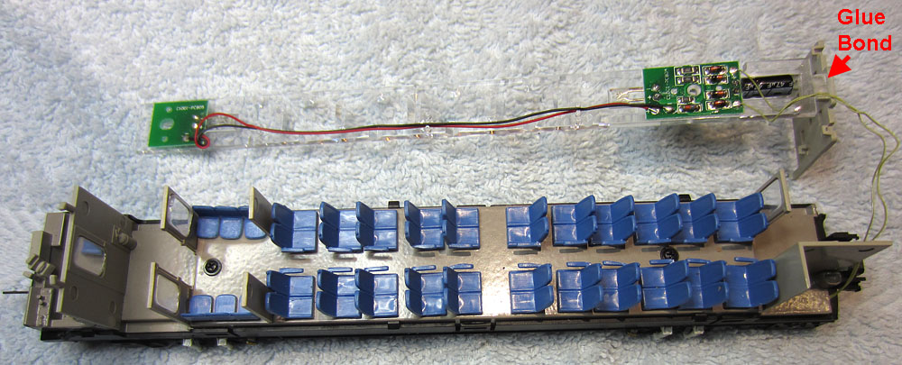
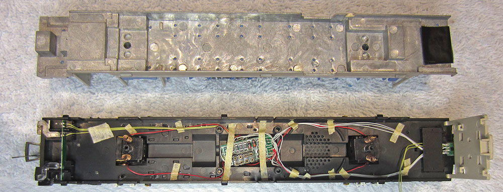
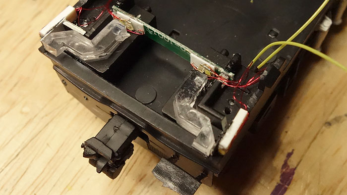
The metal seat base has an enormous cavity between the wheel mounts (compared to the power car).
Plenty of room for a LokSound V4 and a 20x40mm speaker. The original circuit board will have to go though! |
| Details of the
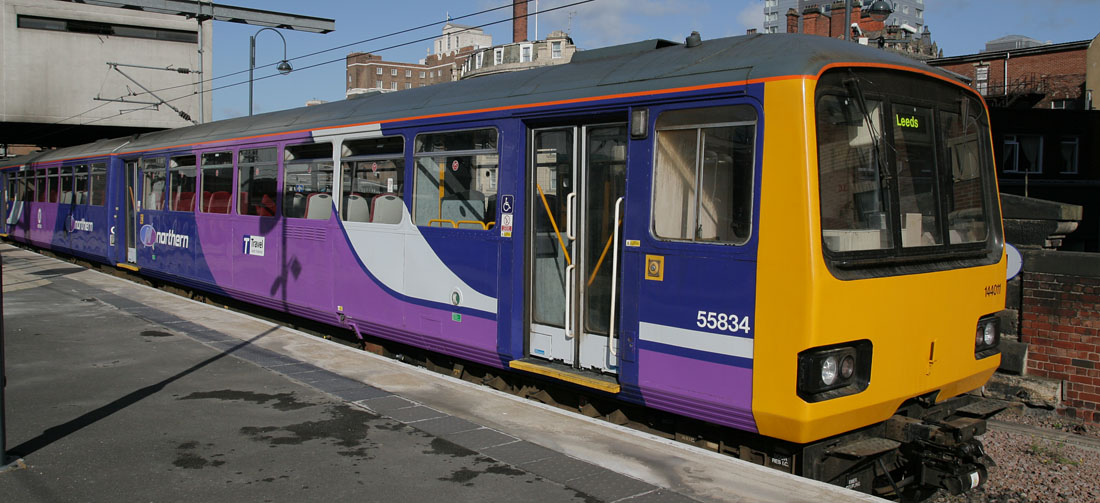
updates: 1) The running lights: Straight out of the box: Day running lights: Too yellow, Headlight too dim, marker light too bright. (Only day forward lights fitted). Light leakage between adjacent lenses apparent when viewed from a side angle.
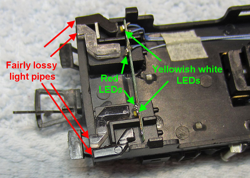
The running lights original internal construction:
LEDs are mounted on a long thin PCB. Light is routed to a point immediately behind the upper body shell mounted lenses via a set of very lossy light pipes.
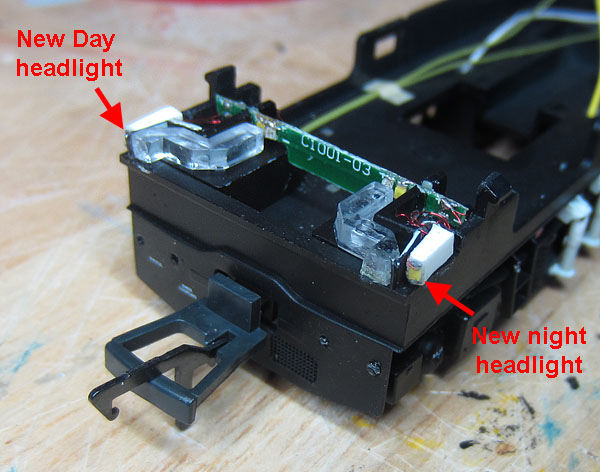
The upper body shell lenses consist of a pair of mouldings, each of which includes two lenses. Night headlights and a night marker light are added. To increase the light level of the headlights, the outer light pipes are discarded and daylight white chip LEDs are mounted near the front of the chassis on plasticard mounts. (Positioned to beam straight into the rear of the outer lenses in the upper body shell.) I had to remove the PCB to change the marker LEDs from the yellowish originals to pure white. This was well glued and required some local cutting by my Stanley knife to separate the PCB from the lower chassis.
Disappointingly, the Chinese design directly couples the two rear light LEDs in parallel and the daylight headlight and marker LEDs are also directly connected in parallel. This is bad practice as LEDs do not always share current equally when connected in this way. The original yellow marker LED on the PCB was replaced with a pure white type. (taking care to get the polarity correct!). An extra pure white LED was soldered adjacent to the right rear light LED to act as the night running marker. The original headlight LED was removed from the PCB. New white LEDs were glued to plasticard mounts fitted in place of the outer light pipes. Black painted plasticard shrouds were fitted between the inner light pipes and the new headlight LEDs, to minimise light leakage between adjacent lenses.
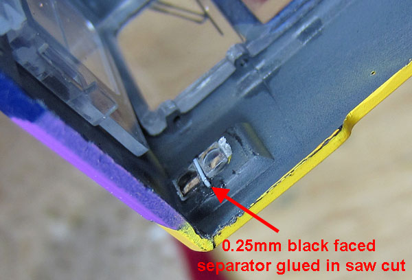
The common lens mouldings used in the upper body shell were carefully split using a razor saw to physically separate the individual lenses and thin pieces of black painted plasticard were glued into the saw slots to act as optical separators.
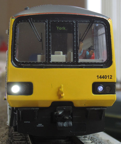
Updated Trailer Car Running Lights:
The headlight LEDs could probably benefit from a very light coating of yellow water colour paint to warm them up a bit: (First tried later in the power car as shown below)
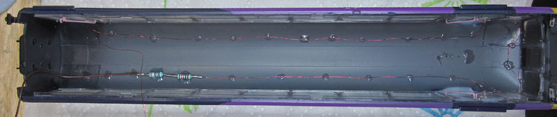
Hazard Lights: The original raised painted hazard lights were carefully flattened and two small holes were drilled through each light base. Amber nanolight LED wires were passed through the new holes and the chip LEDs were glued in place on the original light bases. The LEDs are connected in series, with a common series resistor of total value 6k1, placed in the negative supply. (In the absence of 5k6 or 6k8 values, I had to use a 3k9 and 2k2 in series).
Right hand side on a 14V DC power supply
Left hand side on a 14V DC power supply
Showing the wiring glued to the roof underside
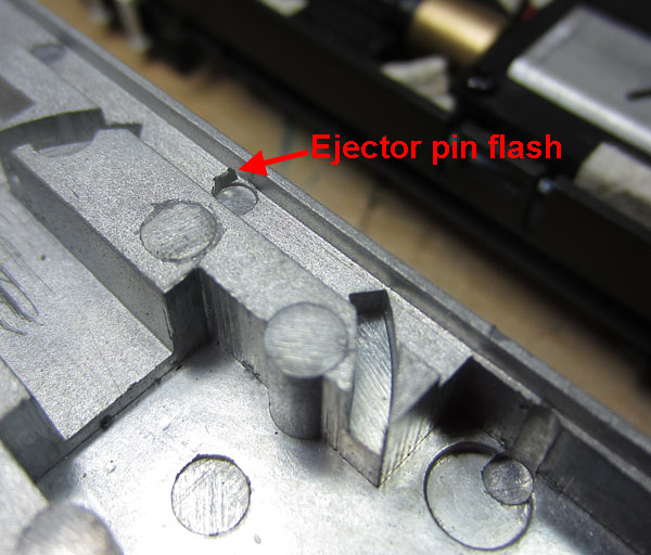
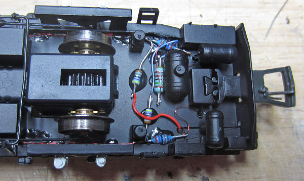
The Power Car: The good news is that after practicing on the trailer car, I managed to remove the power car lighting PCB intact. The replacement marker lights and headlights went into place without trouble, but mounting the FL4 decoder and the interfacing parts in the under-chassis is a much bigger challenge in the power car, where space really is at a premium..... details to follow: Beware! While fine tuning the power car lighting cables on the under-chassis, to keep them inside the narrow cableways in the metal seat base casting above, I noticed a miniature guillotine in the casting, just waiting to slice through the cable insulation of any wires that came too close! The sharp metal flash is very easy to clean up, so if you decide to try any electrical modifications, along these lines.... its well worth carrying out a careful check on the underside of the seat base castings and removing any threats to the wiring that you might find!
Caught this one before it caught me!
Power Car Running lights: The outer light pipes and original day running headlight LED were removed. The yellow marker light LED was replaced with a daylight white type and a similar additional night running marker light LED was fitted. Day & night headlight LEDs were added to beam directly into the appropriate lens, without the use of a light pipe, to dramatically improve the headlight intensity.
The common +ve feeds are all taken from the original PCB.
The LED negative feeds run via holes drilled through the chassis to series resistors below.
The series resistors glued to the underside of the chassis. New wires for a) Forward Day Running Lights (on the right hand side) and b) Forward Night Running Lights (on the left hand side) replace the original forward lights -ve wiring.
Power Car Upper body shell: Basically, a repeat of the trailer car work..... This time, running the razor saw between the front light lenses resulted in one headlight and one marker/rear light lens falling out..... These were glued back in using a non-cyano clear adhesive (Glue 'n Glaze).
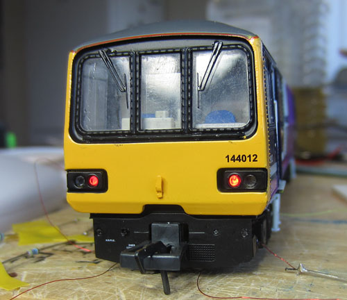
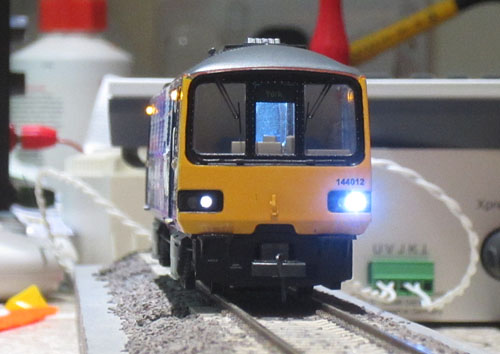
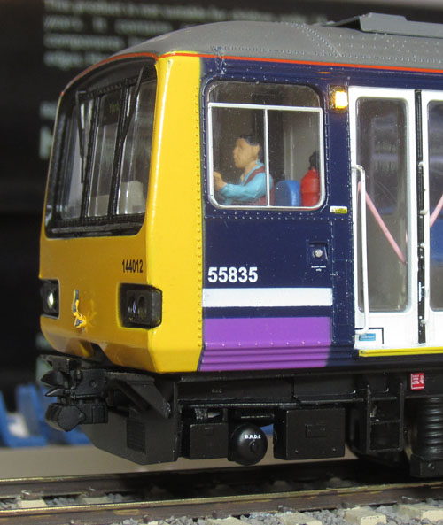
Power car night running lights (under DCC control for the first time.) Hazard lights and internal lights are also operating for the first time. (Chris advises that there is normally a blind pulled down over the driver's internal door window....I can see why now!) |
| Details of the
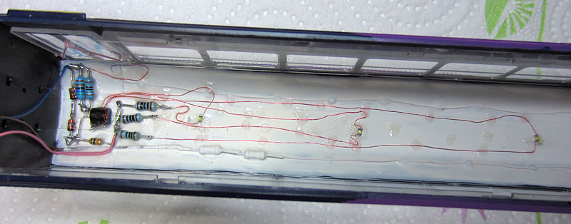
updates: 2. Internal Passenger compartment lighting: The requirement is to find a way to get much brighter lights with anti flicker protection using a max of 1000uF 25V per car. Weird original circuit! The supply is via a bridge rectifier (as its connected directly to the wheel contacts). A 4.7V zener diode is fed via a 2k series resistor from the positive end of the bridge. Across the zener, is a series 470 ohm, feeding two leaded warm white LEDs connected in parallel. With a forwards volt drop of around 3V across the LEDs, that leaves 1.7 volts across 470 ohms resulting in a max current through each LED of 1.8mA..... no wonder they are a bit dim! I've tried running the LEDs in series at around 15mA & the intensity is much improved, but a 1000uF flicker free cap is not as effective as it needs to be with 6V dropped by the LEDs...so I'll remove the original circuit and the lightpipe. Instead, a 15mA current source will drive 3 LEDs in parallel (using 100 ohm series resistors to balance the current). A 1000uF cap works very well with this arrangement. The LEDs will be 0603 daylight white chips, mounted evenly spaced in the roof underside (which will be painted white). The LEDs will beam downwards and draw circa 5mA each. With some simple modifications I think two 1000uF caps will fit inside the toilet. The other circuit parts will be glued to the roof underside. (Separate current sources will be used in each car roof.)
The roof underside was painted matt white and then three daylight white nanolight LEDs were glued to the roof underside. The above circuit elements were soldered together and glued to the roof underside near the rear of the car. Slow drying glue 'n glaze was used, not super-glue, as super-glue fumes can damage the surface of polystyrene windows, causing a hazing effect.
Trailer car roof before the LED wiring and flicker free components are also painted white.
Internal lighting LEDs: On & running at 5mA each at any supply voltage between 4V and 14V.
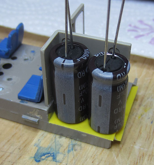
The power car seat base assembly needed modifications to mount the 2 x 1000uF 25V anti-flicker capacitors. After removing the toilet walls from their original location, the toilet base and wash basin protrusions were removed from the casting with a junior hacksaw and file. The walls were then trimmed and re-positioned approx 2mm forward and 2mm inboard of their original position. The floor of the toilet area was then insulated with two layers of electrical tape ready for the caps to be slid in place. Small plasticard wall extensions were fitted to fill the small end-gaps created.
The 2 x 1000uF 25V caps test fitted in the modified toilet enclosure. (The missing seats will be glued back in place when the under-chassis has been finally re-united with the seat base casting.)
Power car interior lighting circuit including 2000uF of anti flicker capacitance.
(I haven't fitted the light shields between the adjacent running light lenses yet.)
First pics of the power car internal lighting (plus hazard lights) working under DCC control. It looks a big improvement on the original internal lighting levels! The caps and roof lighting wires just fit out of sight, within the slightly enlarged toilet. |
| Details of the
updates: 3. Decoders and Sound System:
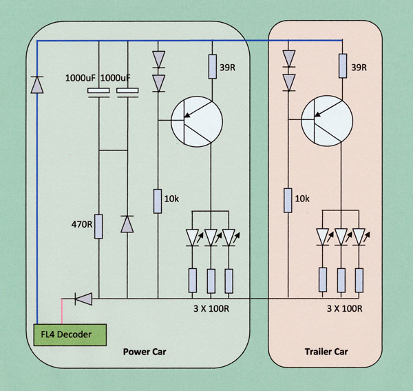
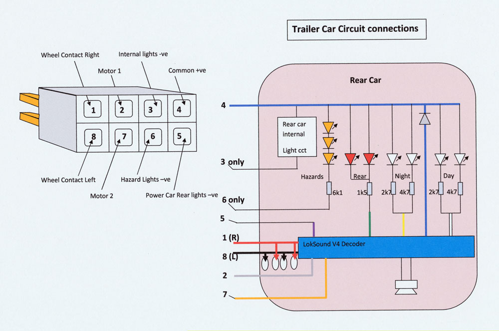
The circuit concept provides full DCC control of the lighting, making use of all 8 ways in the coupling connector between the two cars. An ESU LokSound V4 sound decoder is accommodated in the trailer car and a TCS FL4 function decoder is fitted to the underside of the power car. 4 function outputs are required from each decoder.
Circuit Diagram . (Both rear light sets need to be under the control of the V4 to enable parking with both rears active in either direction.)
The motor and wheel contacts plus the common +ve and power car rear lights -ve, are left as originally wired. The new internal lights and hazard lights -ve connections are as defined above.
Power Car Decoder Wiring: An extra wire was added to the vacant way in the bottom row of the inter car connector and the original "white" & "yellow" directional function wires were re-assigned as indicated above.
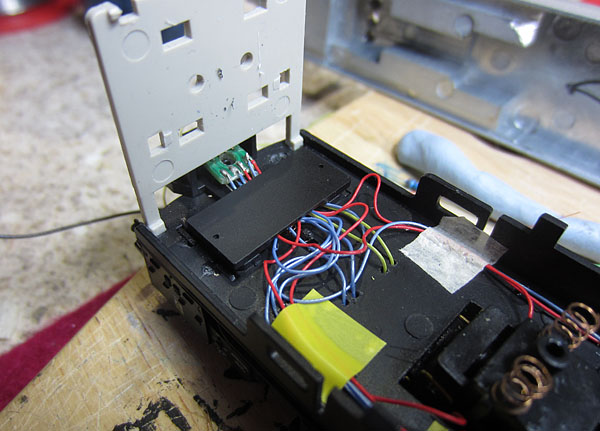
Rear connector re-assembled after the changes. Connections to the new FL4 function decoder are routed through new holes drilled in the chassis floor. The original yellow coloured wires to the Realtrack roof lighting came in handy for the track contact feeds to the FL4!
FL4 glued to the rear chassis floor underside, with a 5 way solder strip glued on top. The two diodes connected directly to the FL4 wires are also glued in place.
All connections wired in place. (The 3 wires to the upper body shell lighting will also connect here.)
The external parts and wiring are largely hidden from view when the train is on the rails.
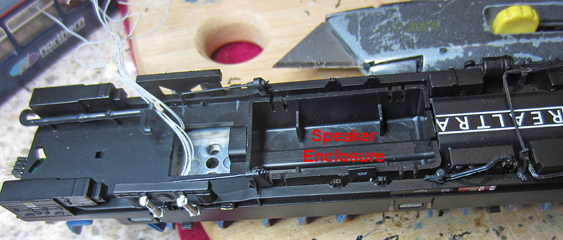
Trailer Car Speaker Installation: There is room for a complete ESU 50334 20x40mm speaker, complete with full size enclosure, in the trailer car, but quite a large hole has to be cut in the under-chassis:
When the fit has been tidied up and the speaker drive unit installed, the exhaust pipe and silencer will be re-fitted.
Drive unit installed and sealed to the enclosure, with the exhaust pipe & silencer re-fitted.
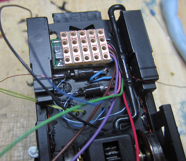
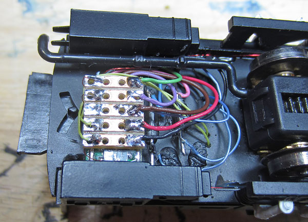
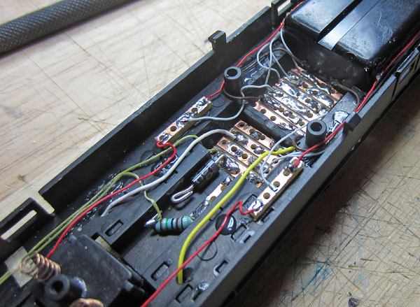
Trailer Car Connector & Decoder wiring Interfaces:
Trailer Car wiring & Decoder Interface Hardware Ready:
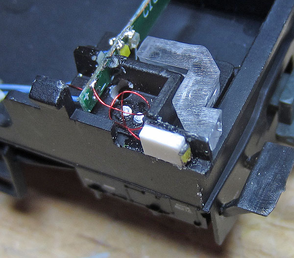
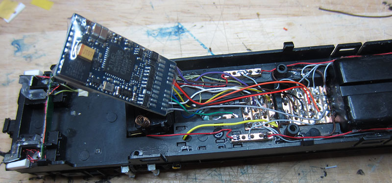
Decoder Location
Decoder wiring connection points. (The decoder wire colours are indicated by the circles.) The decoder wires were trimmed and soldered to the appropriate copper strip, with the decoder resting on the back of the forward wheel box. The decoder was then flipped over, to rest on top of the wiring, between the two lugs, which required a shaving of plastic to be removed for a comfortable fit.
(Photo taken before orange and grey motor wires were reversed to align with the lighting)
Getting the motor control stable: Some adjustments of the motor settings got the loco behaving smoothly at low speeds.... I had to reset CV54 & 55 later to the values shown below to get rid of a mid-speed wobble.......
Setting Up The Decoders To Operate in the Required Manner: Decoder Re-programming (completed using sound slot numbers established from the earlier 142 sound project)
FL4 Decoder Programming
LokSound V4 Programming
A few tweaks to the sound levels:
Function Mapping Summary
|
|
Details of the
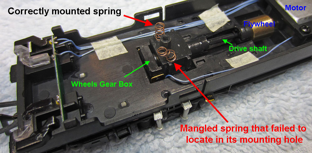
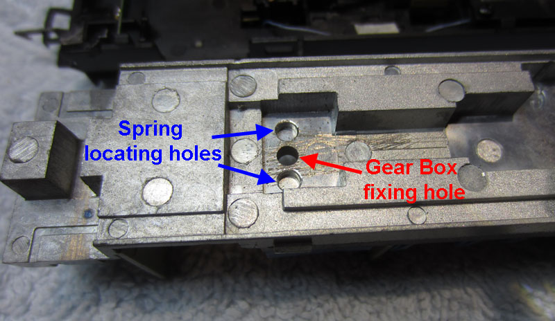
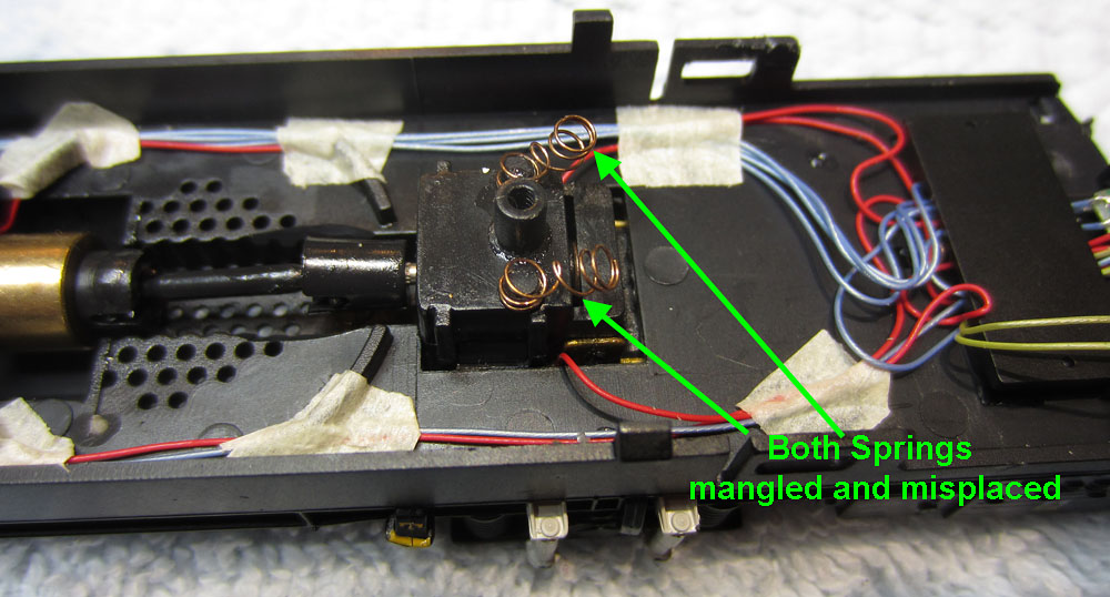
updates: 4) Wheel box suspension spring fitting: A Chinese assembly error was revealed when the first power car was dismantled for the first time. Each wheel pair gear box housing is fitted with twin springs. These should engage in stopped holes on either side of the fixing screw, in the underside of the metal seat base. However 3 out of 4 springs did not engage with the holes and instead were bent over sideways and crushed between the plastic lower chassis and the underside of the metal seat base, ruining the suspension properties.
Separating the cast metal seat base from the clipped-on plastic under-chassis revealed the major assembly error:
Front gear box suspension
Underside of metal seat base.
Rear gear box suspension in complete disarray!
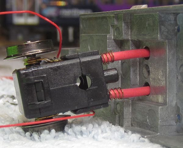
I straightened out the springs and drilled a 2mm pilot hole through the centre of each spring location hole in the metal seat base. Short lengths of 2mm diameter stiff heat shrink sleeving were temporarily inserted through the new holes and then also inserted into the centre of the springs during re-assembly. As the under chassis was brought together with the metal seat base, the sleeving stayed engaged with the springs and was pushed up through the pilot holes, centring the springs as the two assemblies came together. This successfully ensured that the tops of the springs properly located into their recesses. The assembly process is further aided by adding a chamfer to the edges of the stopped holes. Success can be confirmed by visually inspecting the tops of the springs through the pilot holes after assembly. (The spring top diameter is greater than 2mm, so the spring top comes to rest upon the narrow shoulder at the stopped end of the original hole, surrounding the pilot hole.)
Illustrating the technique with the trailer car wheel assembly and metal seat base casting
|
|
Details of the
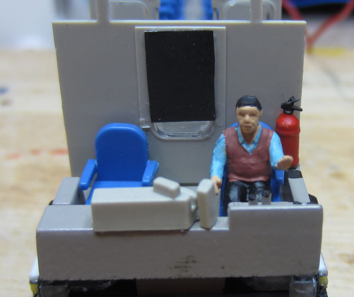
updates: 5) Populating the train: Using contents of the spares box, a Noch driver and several passengers were first added to the power car:
The Noch driver, ready to take control plus a roller blind over the door window.
Several passengers travelling to York in the power car.
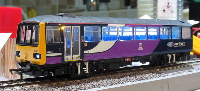
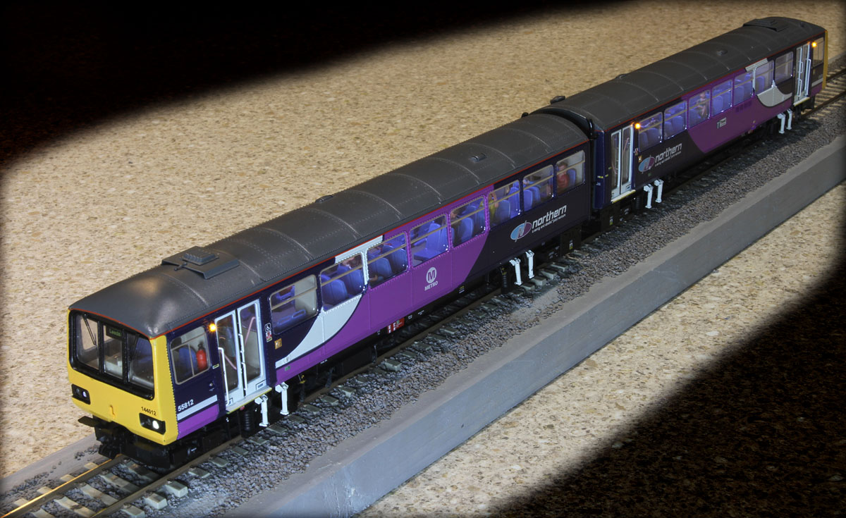
Power car from outside.
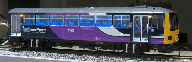
Trailer car passengers added. |
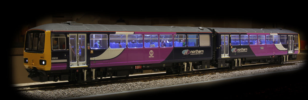
The completed Northern Rail Class 144 with night running lights and internal lighting active.
Hazard Lights on.
The next steps are to generate a computer schedule for the train and to produce a YouTube video to demonstrate operation, including the sound system.
You've read the book (above).... now see how the movie is made:
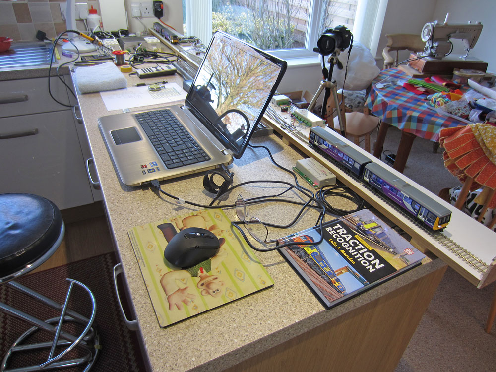
The scene of the crime!: .................on the kitchen worktop!
The Class 144 will be put through its paces on the test track (loft layout still not ready). To give a better idea of the quality of Realtrack's latest model, I'm also running my much modified Hornby Class 142 in a supporting role. However, the 142 sound system will not be active, to ensure that the 144 with Bryan's (Howes) sound project, gets a fair hearing. (Including a couple of custom additions....thanks also to Ben!)
First step is to enter the loco details into the Traincontroller software. (The "Traction Recognition" book, provides some of the data including weight, power and max. speed of the prototype loco.) Next, a schedule is created, for each active locomotive, which includes speed & routing instructions for the loco and details of the sequence to be used for the sound and lighting functions.

The Train controller screen, including train windows for 144 and 142 locos (which can be used for manual control). The pink blocks on the track diagram indicate the loco positions.
Next, the locos are run under PC control, and the schedule behaviour is fine-tuned to achieve the desired result. Finally, both loco schedules are run simultaneously and adjusted to deal with any problem issues. The software controls the points based on the schedule requirements and a series of pre-defined rules.

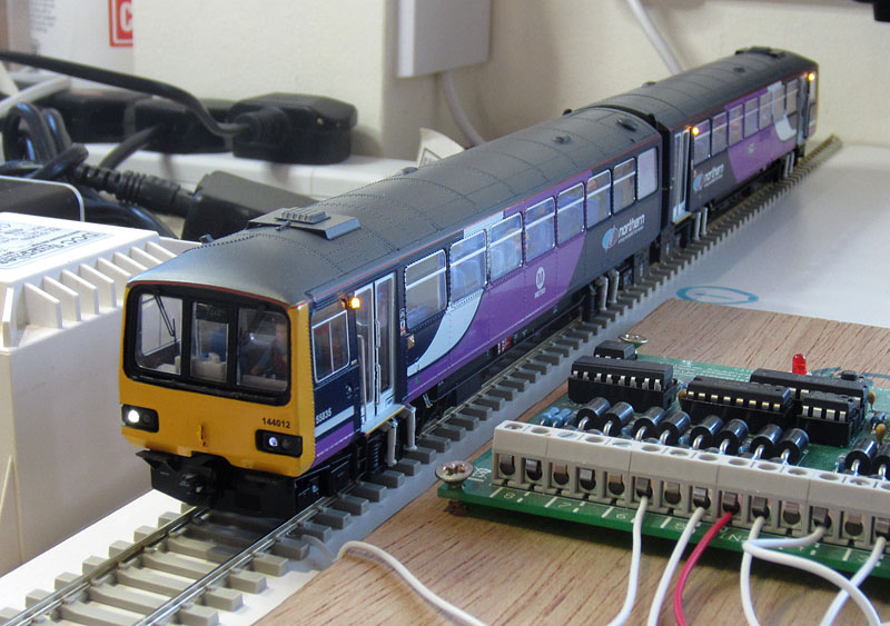
Star of the show, the new 144. (next to the block occupancy monitoring PCB).

Supporting Class 142 at the other end of the track.
Now all I have to do is to make the video....................
My SLR camera can take HD videos, but unfortunately has a hopeless auto-focus capability when in video mode. So I have to run the train movement sequence several times under PC control, placing the pre-focussed camera at the required position for each clip. I then edit the clips together and add the intro still shots plus a bit of mood music, using Adobe Premiere Elements. Finally the labels are added and I can upload the video to YouTube.
Please click here to see the video
A second 144:
|
Sorting out a few additional little problems: The second 144 was updated several months after the first, so I've had to use the above details to remind myself how it was done! This unit uses a Bif 144 LokSound decoder, which will be interesting to compare with the proven Howes 142 unit in the first 144! The power car updates generally went well with just a minor issue on the hazard door warning lights: I used an amber Nanolight LED from an old pack on one side and 2 from a newer pack on the other..... only to find that the newer LEDs were quite a lot dimmer than the previous batch, requiring more current to achieve the required effect. So I had to reduce the common series resistor & add an additional resistor in parallel with the original LED to balance up the brightness. Managed to stab myself in the finger with the Stanley knife when carving out the speaker hole in the rear car..... lots of blood, but no permanent damage! Should have been more careful! The lighting PCB in the rear car demonstrated that when the Chinese get the hang of gluing in a PCB, it stays glued in! I had intended to leave the rear lights in place, but "ping" off the 2 original yellow LEDs then fit replacement white nanolight LEDs. All went well until I accidentally pinged off a rear light while cutting a channel for the Nanolight wires. So I've ended up having to replace all the original LEDs with new ones, glued and wired in, using thin plasticard to insulate the rear & marker lights from the (now unused) PCB tracks. The new rear lights will have individual series resistors this time to set their current. Just ordered a new red nanolight pack from Digitrains, to complete the running light mods..... arrived the following morning!
Day & night replacement rear car running lights. (The displaced front step will be fixed later.)
LED series resistors hidden on the chassis underside. Looks a bit messy, but works fine.
Had 2 faulty open circuit nanolight LEDs in the most recent DCC Concepts 6-pack, when fitting the rear car door hazard lights, so had to order up a new 6-pack from Digitrains to finish the installation.... Really speedy service, with next day delivery again! I've sent the faulty LEDs back to Digitrains, so I'm hoping the next pack I buy from them will have a suitable discount applied.... (Although nothing heard yet.)
|
| Decoder programming, this
time using Bif's 144 LokSound V4:
1) Loksound motor control...... A different set of start values from Bif keep this one stable.....but there's a lot of judder! This one does not run as smoothly as the first 144!
Despite a lot of CV tweaking, there is still a small amount of hesitation jitter in the mid-speed region, which seems to be improving as the drive system runs in. However this unit does not run as smoothly as the previous 144. I think the motor, drive shafts and/or powered wheel pair assemblies are still meeting with intermittent resistance to motion. The back emf system can reduce the impact of the problem, but it can't eliminate it all together! ..... I'll run the loco for a while on the test track and the rolling road. Then, if its still rough, I'll contact Charlie with a view to obtaining some spares for the moving parts. Then I can swop parts til I identify (and hopefully fix) the problem.
2) The Bif Loksound V4 Function Mapping: The sound options have a number of differences compared to the Howes 142 decoder used on the first 144, so it will not be possible to set up an identical function mapping.
CV Changes: ....... Using the ESU LokSound V4 manual, English version, downloadable from the ESU website.
3) FL4 Programming: This is as used in the first 144 except for the brown function output which is transferred to button 5:
All the function changes are now working fine!
Some initial comment re Bif's sounds....... Having become familiar with the internal sounds apparent to passengers on Northern DMUs, I like to make them louder than they would appear from outside the train, so......... I've turned the engine volume down by around 6dB to make the internal sounds more easily heard. This required further adjustments to the external peripheral sound volume settings, to bring them down to better match the engine (e.g. horns, flange scrape etc). It works well, with a new feature: a recorded Northern Rail safety message, which I guess is played as the train pulls away from each station stop. Detailed Volume changes:
Further tinkering with the function mapping: To simplify manual control of the station stop-start sequence, I've re-arranged several functions to better group the essential buttons on the Lenz controller. I won't produce tables of these CV changes as they are very user specific & can all be derived using the ESU LokSound V4 manual function mapping section. The resulting function list is shown below. (The volume boost can be used to give a bit more punch to the engine sounds as the train moves away.... if this is useful.)
The definitive 144 number 2 function mapping list ???
Adding Passengers and thinking about a video to show both 144s working together....... I think the indications are now fairly positive on the jitter front, as its definitely getting better as a result of a few extended high speed runs on the rolling road! So I'll get some passengers on board before refitting the upper body shells. Body fit problem on the power car: While the rear car lights looked fine, those on the re-assembled power car were much dimmer. Investigation revealed that the upper body shell clips were pulling the front down too far, so that the chassis mounted light sources no longer aligned properly with the body shell lens apertures. After an hour or so of careful trial and error Stanley knife work on the front and centre clips plus their attachment slots, I got the front up high enough to cure the problem. The interior lights and hazard lights in both cars, connected for the first time to the decoder, work fine. More running in required before I start any demo video work! (Still a bit of residual hesitation in the mid-speed range.)
To see a You Tube video demonstrating the Legomanbiffo Decoder and the original Howes 142 Decoder in operation on the two 144s: Please click here |
| Supplier website links:
The photos of real class 144s were taken at Leeds & York in recent years. The photos of the model are taken on the kitchen worktop using a Canon Ixus & DSLR. |