|
DCC fitted Hornby Class 153 conversion to incorporate newer style light fittings.
|
|
Introduction: The availability of new full size light emitting diode technology dual function marker and rear light units has resulted in many Class 153 Single car Diesel units receiving mid-life lighting updates. This webpage shows how the new lighting arrangements operate and documents the update of a DCC fitted Hornby Class 153, with this type of lighting. Note that the smaller pictures can be enlarged by clicking on the image. |
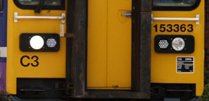
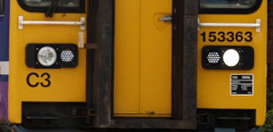
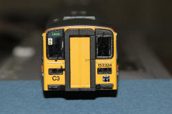
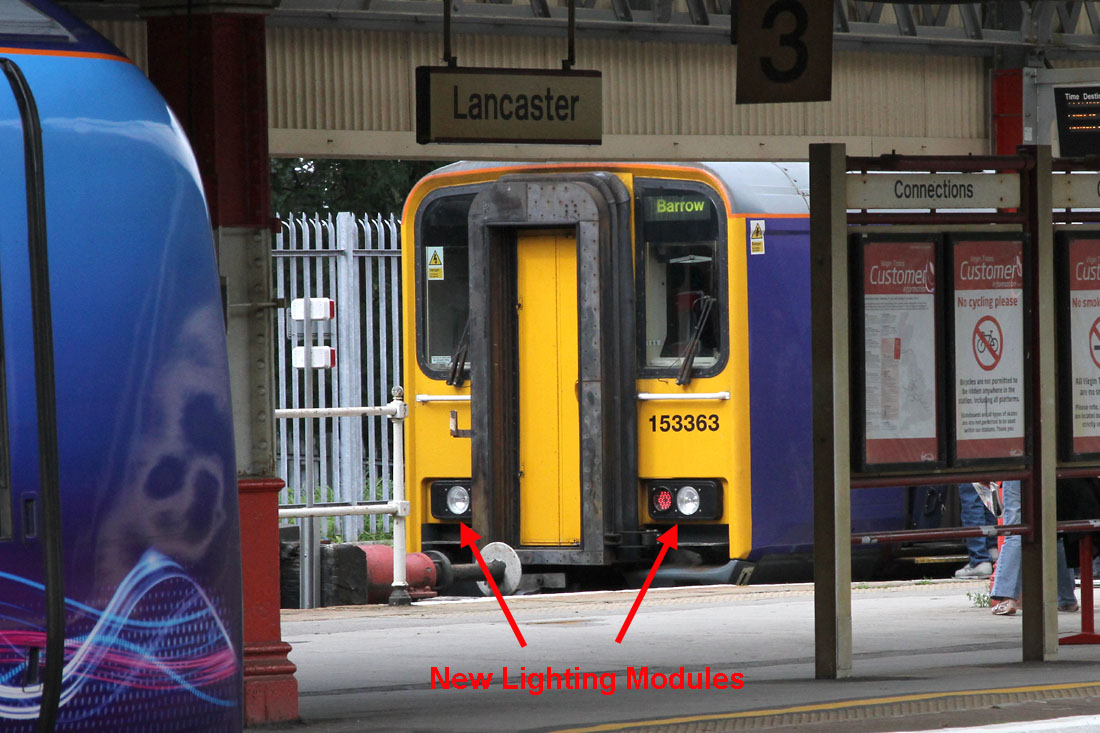
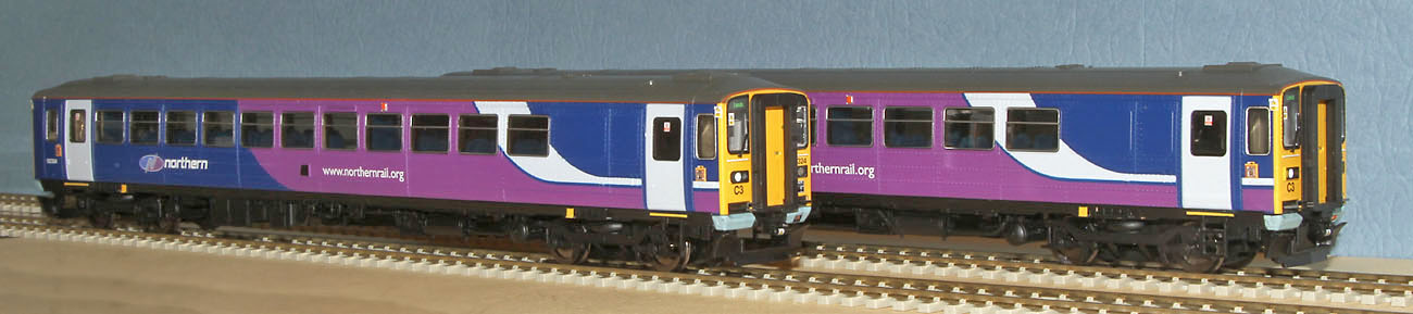
Northern Rail Class 153 at Lancaster, fitted with new LED marker / rear Lights (both rear lights on at this end)
| The Modified Lighting
Assembly: The photo above shows the new lighting modules. Each of the 4 modules fitted to a 153, contains a headlight outboard and a dual purpose LED lamp inboard that can act either as a red rear light or as a white marker light. At the forward end of a 153, both white marker lights are active with either the right hand headlight, during day running, or the left hand headlight, during night running. At the rear end of the 153, both rear lights are active. The original rectangular marker lights used in early 153s are completely absent from the new light housings. |
|
Day running lights |
Night running lights |
| The DCC fitted Hornby
Class 153 motor control and lighting control: As the Hornby 153 was almost obsolete at the time of purchase, I took the last DCC equipped unit stocked by Rails of Sheffield rather than risk not being able to find a DCC ready variant elsewhere. Once CV 3 and CV4 were increased, the on-board decoder motor control worked well, so I propose to retain the Hornby decoder for the initial build, but maybe add an additional TCS FL4 function only decoder, if I decide to add additional effects at a later date (such as hazard lights). |
| Modelling the new lights......
the plan: The Hornby light pipes and LEDs will be removed, to be replaced by discrete LEDs. The rectangular apertures for the old style marker lights will be filled. The headlight aperture will be set at 2mm at both ends to accommodate white tower LEDs. The dual function marker/rear lights will be made using white tower LEDs, turned down to 1.5mm lens diameter, with red chip LEDs glued to their sides. Paint will be used to prevent unwanted light leakage between headlights and marker/rear lights. |
|
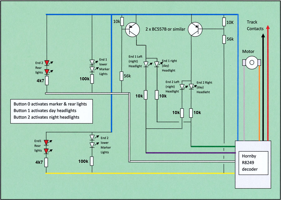
New Hornby Decoder Circuit diagram: The Hornby R8249 decoder claims to have 4 function outputs. However, there is no guidance in the data sheet about how the third and forth functions operate. From what I can glean on Google, it appears that buttons 1 and 2 are used to switch the green and purple wires in a simple on or off manner. As it does not appear possible to incorporate direction of movement as a condition of function 3 and 4 operation, two transistors, driven from the directional white and yellow function 1 and 2 wires will be required to enable only the forward headlights, while the green and purple function 3 and 4 wires select day or night headlights respectively.
|
|
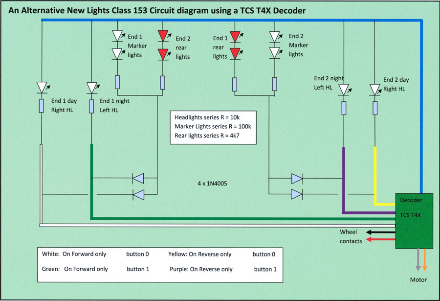
Alternative TCS Decoder
circuit: A simpler circuit could be used if a TCS T4X decoder is used in place of the Hornby device. All the TCS function outputs can be programmed to be direction sensitive. This removes the need for switching transistors. If the Hornby circuit results are unsatisfactory, this will form the replacement solution.
Button 0 is used for Day Running. Button 1 is used for Night Running. |
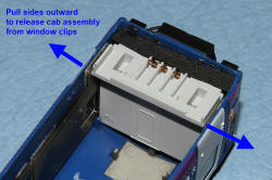
| Dismantling the Hornby
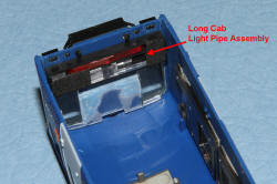
Class 153: The lower edges of the upper body shell need to be gently pulled outwards to release the clips holding the upper body shell to the chassis. Using a small screwdriver, apply outwards pressure to the inside of the side wall below the windows, through the space behind the motor bogie. As the crack appears between the side wall and chassis, insert a thumbnail, swiftly followed by pieces of card to separate the chassis from the side wall clips. Repeat on the other side, then gently extract the small cab end of the chassis from the upper body shell. The chassis mounted cab at the long cab end must be extracted from its light pipe assembly to finally separate the chassis and upper body shell. |
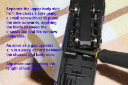 Creating a gap between chassis & side wall |
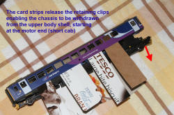 Separating the chassis & upper body shell |
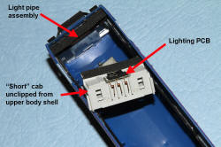
| Removing the original
light pipes and lighting pcbs: The light pipe assemblies are situated at each end of the upper body shell. These are held in place by the lenses on the end of the light pipes and can be extracted by carefully pulling the black plastic frame away from the rear of the car ends, after first unclipping the short cab from the upper body shell.
The lighting PCB assemblies are fixed to the front face of each cab assembly. They are removed by levering away from the cab front.
|
| Lighting aperture
modifications: The original rectangular marker light apertures are filled flush with the front face of the light housings, using a suitable polystyrene modelling filler. The undersize headlight apertures at the long cab end are drilled out to 2mm diameter. The front face of the light housings are then painted with satin finish black modelling paint. (The rear/marker
light apertures remain at their original 1.5mm diameter and the
tower LED lens cylinders will be trimmed and reduced in diameter to
fit.)
|
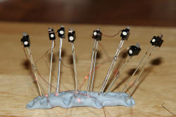
| The new dual function LEDs....
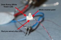
first some experimental work: A red "nanolight" pre-wired chip LED is super glued to the side of a pure white tower LED. (The exact location of the chip on the body of the tower LED for brightest red output was found by experiment). A coat of white paint over the whole assembly dramatically increased the red light intensity. However, quite a lot of light escapes through the white paint, so a final coat of gloss black paint will be required to prevent unwanted light leakage in the finished Class 153.
The final series resistor values will be determined when all the LEDs are trimmed, painted and fitted to the upper body shell. The remaining rear/marker light tower LEDs will be trimmed and reduced in diameter before the chip LEDs are glued in place!
4 x 2mm headlights & 4 x 1.5mm dual red/white LEDs. Trimmed, painted, polarity marked and ready to go! |
| Fitting the LEDs to the
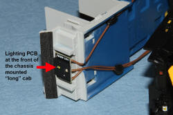
cabs and cab fronts: To accommodate the rear bodies and terminal wires of the LEDs, the cabs need to be modified. The long cab is first removed from the seat moulding, so that it can ultimately be fixed into the upper body shell. The rear walls of the cabs are removed and the seats are cut from the front cab assemblies and glued in place on the rear cab walls. Rectangular holes are then cut in the cab front below the dash boards, to correspond with the location of the LED rear bodies and terminal wires. The LEDs are inserted into the rear of the lighting apertures and fixed into position with the lens front face flush with the light housing front panel. The cab fronts are then clipped or glued into place. Holes are drilled in the cab back walls to enable the LED leads to pass through. The cab rear walls are then glued back in place with the LED leads threaded through the holes.
Long cab removed from chassis and fitted in upper body shell with LED leads passing through the back wall (The LED leads support the cab in place). |
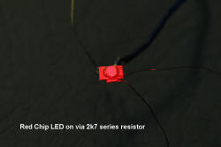
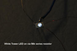
| Optimising the LED series
resistor values: Temporary connections are soldered to the LED leads to enable the LEDs to be powered via series resistors from an external DC power supply. Various resistor values were tried, but in the end, I settled for 100k for the marker lights, 4k7 for the rear lights and surprisingly, 10k for each of the headlights. I would normally expect to use a much smaller headlight series resistor, but on this project, for the first time, I applied a coat of reflective white paint, followed by an overall coat of opaque black paint to each headlight tower LED. (In a similar way to the dual purpose rear/marker LEDs). The white paint must have greatly increased the light output, enabling the headlight LEDs to be run at much lower current than if I had just applied the usual coat of black paint (to suppress light leakage)..... a useful lesson for the future! |
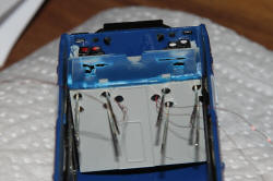
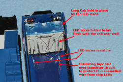
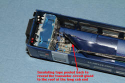
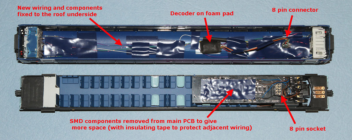
| Wiring up: The LED leads emerging from the cab rear walls are bent and formed to lie flush with the rear cab walls. The upper body shell window inside surfaces are temporarily protected from soldering fumes using masking paper and tape. The series resistors for the LEDs are mounted on the roof underside & wired to the LED leads at the rear of the cab walls. The transistor circuits (one at each end) are pre-assembled and fixed to the cab roof. The wires interconnecting the components are routed and fixed in the underside of the roof. The Hornby decoder is carefully removed from the main PCB and is then also fixed to the roof underside (by a piece of double sided foam tape). The decoder is located so that the NMRA plug will reach the PCB socket in the chassis unit. The decoder blue, yellow, white, green and purple wires are disconnected from the NMRA plug and re-connected to the appropriate lighting wires in the roof underside.
In the chassis unit, the original Hornby surface mounted components are removed from the main PCB to make more space for the decoder and wiring. The thin "nanolight" wires are protected from accidental short circuits by strips of insulating tape, used to cover the transistors, some resistors and exposed conductors, before these vulnerable wires are laid in place.
Chassis and Upper body shell ready to be re-assembled |
| CV programming:
The Hornby decoder R8249 has very few programmable CVs. The only changes from the decoder defaults applied were CV3 (acceleration delay) set to 16 and CV4 (deceleration delay) set to 12. (Plus of course the new address number). |
| Cosmetics: The obstacle deflector blades and coupler sockets are cut away from the bogies. "Soiled" pale blue paint is applied to the body underside at each end of the car. New brackets for the obstacle deflector blades are fabricated from plasticard sheet, then glued to the deflector and chassis underside below the cabs, using photographs of real 153 units to correctly position the deflectors. |
| Lights testing The lights all worked as expected but the Hornby forward cab default was found to be the short cab. This was switched to the preferred long cab by simply refitting the 8 way plug turned through 180 degrees. (Only possible because just the motor wires and track contact wires were connected to the plug........otherwise, CV29 could have been set to 3 to achieve the same result.) |
Light levels in the photos below are kept low to show the relative LED light levels and colours
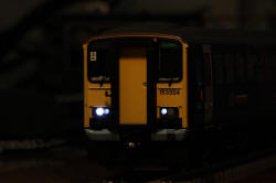 Long cab end day running
|
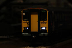 Long cab end night running
|
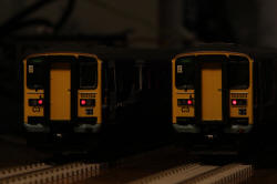
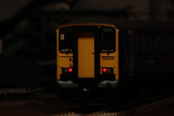 Long cab end rear lights
|
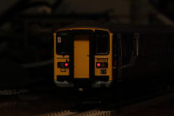 Short cab rear lights
|
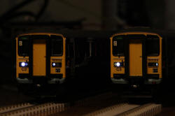
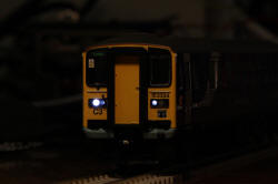 Short cab end day running |
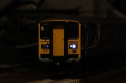 Short cab end night running |
|
Problems and fixes: The headlight and marker light LED apertures were a shade too close together, so the LEDs were slightly splayed, presenting some marker light lenses at a slight angle. Use of smaller bodied tower LEDs from DCC Supplies would have overcome the problem but unfortunately they were nil stock at the crucial time. (A thin coat of glue 'n glaze over the worse lens front remedies the appearance.) The good news is that the Hornby decoder functions 3 and 4 work as expected and the dual colour light concept works well! Also, the white undercoat applied over all the tower LEDs prior to the black top coat, increases the output light levels significantly, enabling the LEDs to be run at a lower current, while the black top coat prevents unwanted light leakage. |
Below: The finished new tech lights Northern Class 153 with its older lights stablemate:
 Daylight running |
 Rear lights |
Northern 153s
| Supplier website links:
The photos of the real Northern Class 153 were taken at Lancaster during Sep 2010. The photos of the model were taken on the kitchen worktop or floor at 200 ISO, using flash. |