|
Adding Sound, Hazard Lights and internal lighting to a DCC fitted Hornby Class 153 conversion already modified with newer style external light fittings.
|
|
Introduction: The 153 unit, already fitted with new style external lighting, is to be further modified, to incorporate sound, hazard lights and working interior lighting. This webpage shows the initial plans for the update and how the modifications are really installed. |
Northern Rail Class 153 at Lancaster, fitted with new LED marker / rear Lights (both rear lights on at this end)
| An Outline of the Proposed
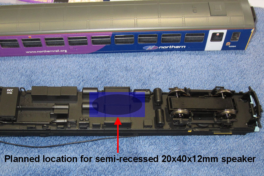
Approach: The original Hornby decoder will be replaced with an ESU LokSound V4 decoder with 8 pin connector, combined with a TCS FL4 function decoder. The use of two decoders rather than adding the LokSound adapter with Aux3 & 4 amps is intended to minimise the head height of the roof mounted decoder circuitry, keeping it all above window level. Amber chip LEDs will be fitted into recesses cut through the hazard light mouldings. The inside of the passenger area roof will be painted white and discrete chip LEDs will provide internal illumination. An ESU 4 ohm speaker (40x20x12mm) will be mounted semi-recessed in the underside of the chassis, largely hidden behind the underside mouldings. |
| Opening the unit up and
dismantling the chassis:
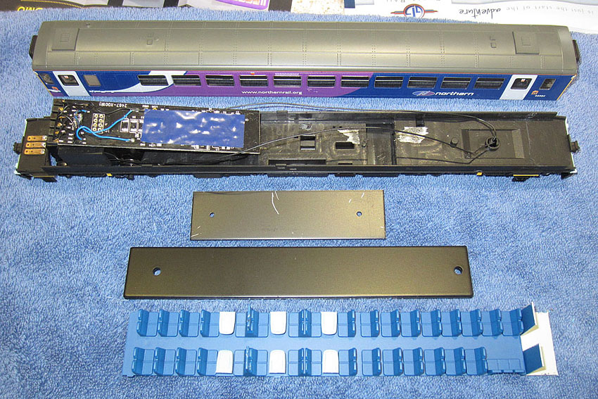
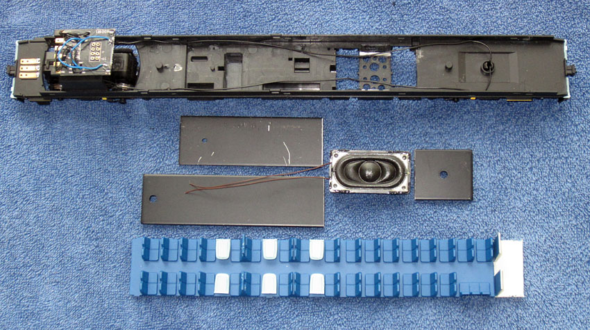
The picture above shows the upper and lower body shells after the previous modifications.
Dismantling the chassis unit: Under the seat moulding are steel plates to provide extra adhesion weight and stiffen the chassis. These need to be cut to make room for the new speaker enclosure. A hole will also be cut through the base of the chassis for the speaker. The original Hornby PCB assembly will be truncated just inboard of the 8 pin socket, to give better illumination of the passenger compartment. The 8 pin socket will be used to electrically connect the chassis and upper body shell.
The speaker will be fitted approximately as indicated above, partially hidden by the underside mouldings |
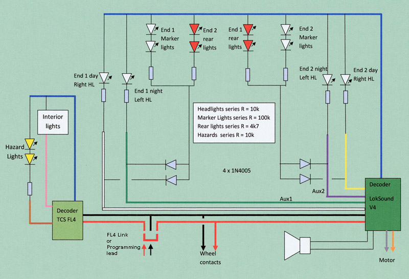
| The Circuit Diagram:
The switching transistors used with the previous circuit will be removed and the remaining circuitry will be re-built as shown above. The two decoders are connected in parallel to the track contacts in operation, but for programming, these connections need to be accessed separately for each decoder. A link plug (on the loco underside) is used to connect the FL4. This must be removed for programming activities. A programming lead is then used in place of the link plug to adjust CVs in the FL4, while the LokSound can be programmed on the track in the normal way as long as FL4 link plug is removed.
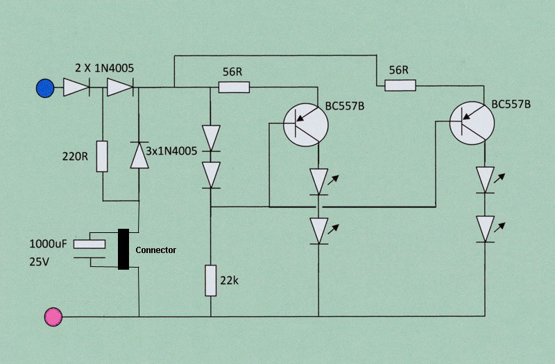
Interior lights circuit: A pair of 9mA constant current sources with anti-flicker reservoir capacitor |
|
The probable revised Sound and Lighting Button Mapping:
|
|
Sourcing the decoder: The Howes Class 153 decoder is the preferred choice, based on their successful Class 150 decoder. (The 153 uses the same engine.) Bryan and Howes have agreed to add the missing guard's whistle to the sound files.
|
That's the plan, next I've got to build it!
| Modifying the chassis
assembly:
The PCB assembly was shortened using a junior hacksaw, retaining the 8 pin socket, with tracking to support the motor connections, wheel contact wires and the new speaker wires. The steel plates were sawn through to clear a gap for the speaker and the chassis underside was cut away to provide space for the speaker to be mounted semi-recessed above the battery boxes. The speaker will be installed facing downwards, held tightly in place by a foam pad under the clipped in seating moulding.
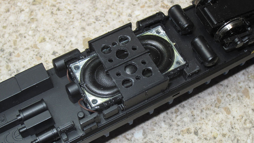
The speaker installed in the chassis.
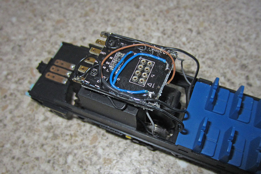
Redundant tracks on the truncated PCB used to connect the speaker (grey wires) to two inner sockets in the 8 way connector and the FL4 programming lines (black wires) to another inner 8 way socket plus the wheel contact wires.
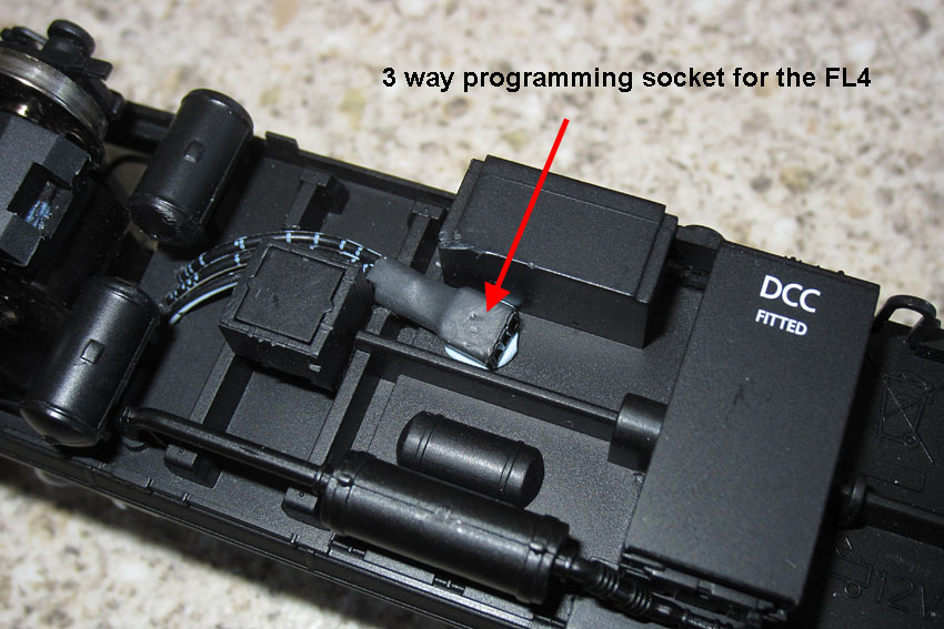
FL4 programming socket Blu-Tacked to the underside.
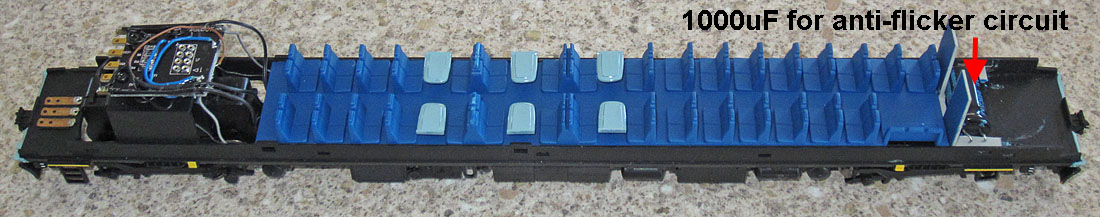
The completed chassis assembly, including a large capacitor for the lighting anti-flicker circuit at the rear below the door window level. |
| Modifying the Upper Body
Assembly:
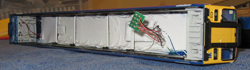
Rear end of upper body showing the Internal lighting current sources and FL4 decoder bonded to the roof The 1000uF capacitor on the chassis assembly will be connected to this circuit.
LokSound Decoder bonded into roof underside with NRMA 8 pin socket connecting to the chassis
Internal lighting LEDs on cross beams, facing the white painted roof underside (& white painted decoders) |
| Finding the sound slot
assignments: The sound slot numbers are established, by dropping the volume to 30 for each sound slot in turn and pressing the function buttons to find which sound is reduced. The master volume was first reduced significantly then minor adjustments were made to the relative sound levels.
Next, a button remapping exercise:
LokSound CV changes to carry out the remapping: Using data from the May 2012 LokSound manual. The lines are those in the table on page 52
FL4 CV Programming:
Summary of the revised function mapping:
|

Link plug inserted to activate the FL4 decoder after programming (Held in place with Blu Tac)
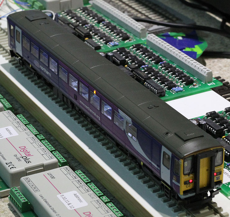
| The completed 153 running under
computer control on the test layout:
Internal lights on
Hazard lights on (amongst the decoders and track occupancy detectors ready for phase 1 of the loft layout.)
The sound system also works very well, a definite success Bryan!! Just one minor problem: At the minimum speed step, there is a small amount of juddering. This clears at speed step 2, with smooth running for all other speed steps. This is a good opportunity to try the new ESU self-calibration system to automatically establish the optimum motor control CV values for this particular motor. The procedure is to program CV 54 with the value zero, then, with the locomotive heading towards a long straight section of track, press function key number one. (It's crucial to make sure the direction of travel is correct first.) The loco moves away at high speed, then slows to a stop. The motor control CVs (51 to 55) are automatically optimised during this process.
I set up over 4m of straight track to make sure there was enough, but it needed less than 2m to complete the process. The motor ran more smoothly, but was still exhibited a tiny amount of judder on speed step 1. After similar problems were addressed with my Class 156, I found a little bit of CV51 & an increase in CV52, beneficial for these low inertia motor systems. This worked well on the 153 as well! Running variable frequency drive also helps via CV124.
Project complete!
To see a YouTube video clip of the Class 153 on my test track: Click Here
|
| Supplier website links:
The photos of the real Northern Class 153 were taken at Lancaster during Sep 2010. The photos of the model were taken on the kitchen worktop, using a Canon Ixus 220HS. |