Click on the smaller images for a larger picture
|
DCC conversion and Lighting update of the
Hornby Class 156 two-car DMU.
Click on the smaller images for a larger picture |
|
Please be aware that this webpage is now over 10years old.
Many of the parts described below are no longer available.
However in most cases better solutions can now be sourced.
|
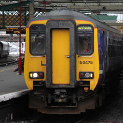
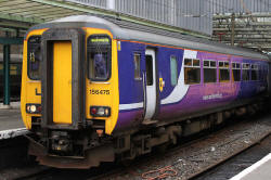
Introduction: This document provides a summary of the process adopted to incorporate DCC decoders, correctly operating external LED lighting, trailer car electrical track pick-ups and snow-plough / obstruction protectors to the Northern Rail variant of the Hornby 2-car Class 156 unit (OO gauge). Note that (most of) the smaller pictures can be enlarged by clicking on the image. |
Hornby sales pic. of the original Settle-Carlisle 156 pair
| DCC Conversion Approach: The plan is to use a 4 function and back emf motor controller TCS MC4 decoder in the power car and a 4 function TCS FL4 (function only) decoder in the trailer car. The Hornby Class 156 trailer car has no electrical track pick-ups provided. In order to facilitate these inputs to the FL4 decoder, either a pair of wires could be fitted between power and trailer cars, or home made pick-ups need to be constructed for the trailer car bogies. (The latter was chosen as the preferred approach). External Lighting Modifications: The Hornby model is not fitted with operating lights. However, the light housing units and lens fronts are correctly modelled. The original headlights and rear lights will be drilled out, leaving apertures ready to accommodate 2mm tower LEDs. The side marker lights will be illuminated by yellow tinted white tower LEDs beaming into the rear of the clear plastic moulded marker light lenses. All LEDs will be painted black except for the tower end, to prevent unwanted sideways light bleed. On the real Northern Class 156s, during day running, the right hand headlight and both marker lights are used in the forward car. During night running, the left headlamp and both marker lights in the forward car are used. It is planned to arrange for the DCC decoder programming to handle day and night running of the lights via function buttons 0 and 1 respectively. |
|
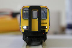
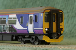
Day running lights |
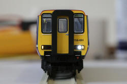
Night running Lights |
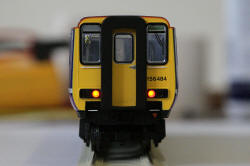
Rear Lights |
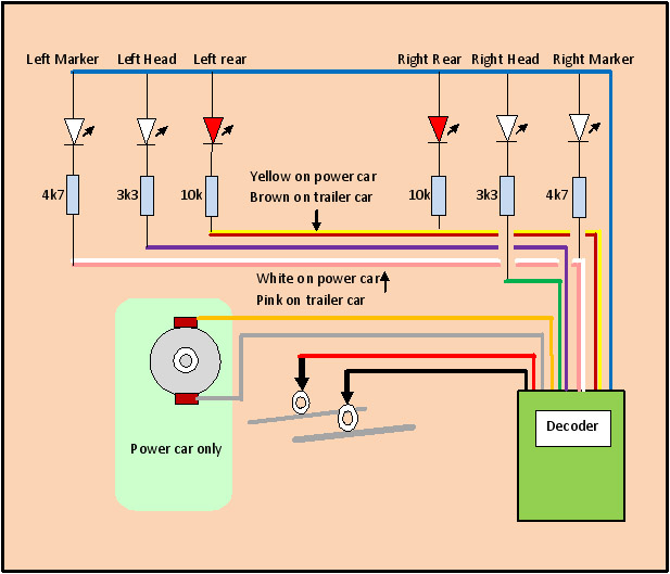
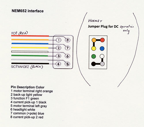
| Circuit Diagram for
lighting and power car connections:
The resistors control the current flowing through each LED. This determines the intensity of the light generated by the LED. The values were established by experiment, for the LED types employed. Some adjustment may be required if different LED types are used. |
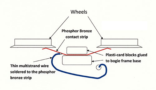
| Electrical pick ups for
the trailer car: The Hornby model uses wheel sets that have isolating bushes between both wheels and the axle. To fit pick-ups to these, rear wheel face pick-ups are required, using phosphor bronze strip. Suitable strip material is manufactured by Albion Alloys and can be obtained from good model shops (mine came from Trains 4 U in Peterborough). The strip is carefully bent to apply light pressure to the rear face of the wheels. Plasticard blocks are super-glued to the bogie frame base to hold the centre of the strip in place. When the strip is correctly located, it is fixed between the blocks using super-glue. Very thin, very flexible multi-stranded wire is then soldered to the phosphor bronze strip (close to the fixing point). The wire is arranged to pass from the bogie through the floor of the loco, without impeding the movement of the bogie.
This arrangement replaced a simpler technique fitted previously, that used some old Lima wheel sets I had from a very old Lima class 156. The newer Hornby wheel profile works successfully on code 75 rail, but the earlier Lima wheel flanges are too deep to permit code 75 operation. hence the need for the change. |
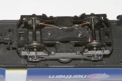 New contacts on Hornby wheel sets |
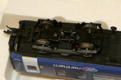 Original solution with Lima wheel sets |
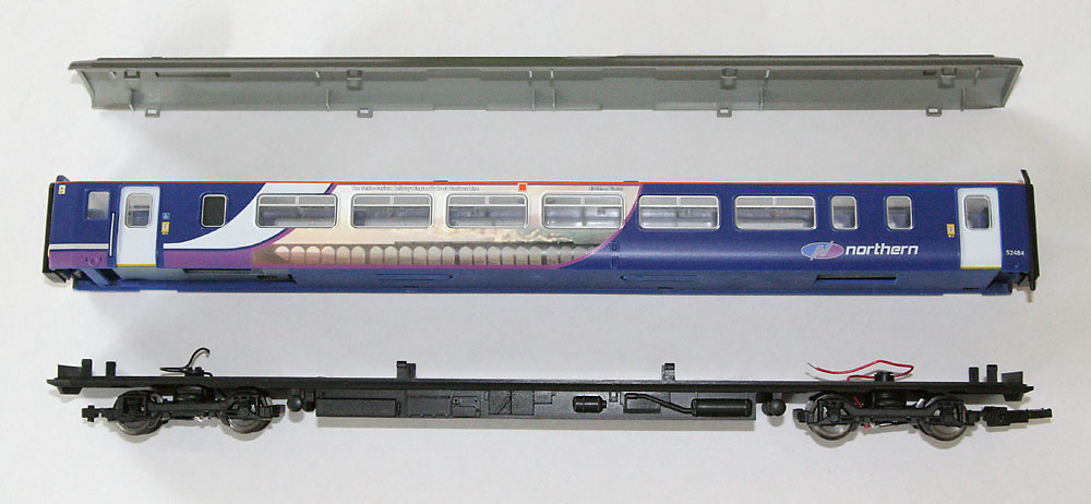
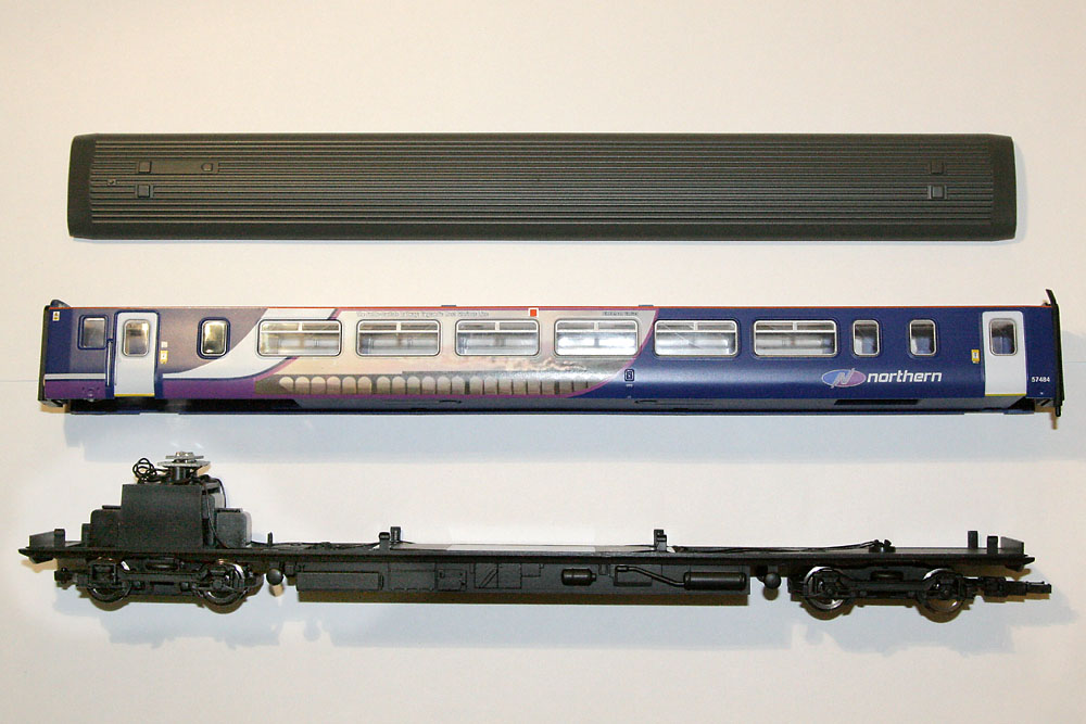
| Achieving Access to the
trailer car: First the upper body shell must be separated from the wheeled chassis unit. The lower edges of the sides are carefully prized away from the chassis unit to release the 8 plastic clips holding the two parts together. This is not an easy operation! The roof can then be removed from the upper body shell by releasing the eight clips holding these two parts together. (See picture below for the location of the clips.) The picture was taken after the wheel contact modifications. |
| Preparations to
accommodate the new LED lighting: The clear plastic headlight lenses and red tinted rear light lenses were first drilled out. Initially a 1mm drill was used and the hole re-centred with a circular needle file. the hole was then progressively widened, using a 1.5mm and then a 2mm drill. The LED devices were painted black overall except for the leads and the top surface of the tower, to prevent light leaking between adjacent devices. The cathode of each LED was then marked with a white dot, to avoid subsequent uncertainties on polarity after the leads have been trimmed. The plastic cross-piece behind the light locations in the upper body shell was then removed to enable the LEDs to be installed from the rear. |
After drilling out the original head and rear lights
| The new LEDs: The LEDs are 2mm tower types available from specialist suppliers such as DCC Supplies and Bromsgrove Models (see end of article for website links). The new LEDs should be a tight fit and when inserted in the 2mm holes and wired together with their resistors, they are robust enough not to require a supporting PCB. |
| Fitting LEDs to
front-piece: The headlight and rear light tower LEDs are pressed home until their front face is almost flush with the front of the light housing. The marker lights are mounted to beam at the rear of the clear plastic moulding, directly behind the marker light lenses. (A common anode wire is created for head and rear lights and the anodes of the two marker light LEDs are soldered to this, holding the marker light devices in place. The other leads are trimmed and formed ready to mount the resistors.) |
LEDs fitted in drilled out holes
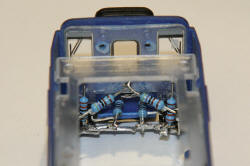
| Adding current control resistors
and the FL4 decoder: The resistors (as shown in the circuit diagram above) are mounted on the floor of the driving cab on the trailer car, taking great care to avoid short circuits. The circuitry is kept low to hide it from direct view through the driver's windows. Attachment points are built in for the decoder cables. The FL-4 decoder fits conveniently adjacent to the rectangular hole in the base of the upper body shell in the compartment immediately behind the cab. It is attached with an adhesive foam pad. The appropriate decoder wires (as shown in the circuit diagram) are connected to the LEDs. The red and black decoder wires are reserved until the upper body shell is reunited with the chassis. |
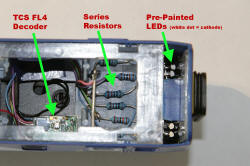
Decoder, resistors and LEDs in place
| Mating the upper body
shell and chassis: The track contact wire from the front bogie emerges directly into the compartment containing the decoder. The rear bogie cable is routed through the passenger compartment as inconspicuously as possible, and up into the roof section. From there it is routed above the passenger compartment and into the decoder compartment for connection. The LED bodies in the upper body shell clash with the front top edge of the chassis unit. The chassis moulding must therefore be filed down locally at the problem points in order to make a flush fit. The upper body shell and chassis can now be pressed carefully together till the 8 clips are fully engaged. The wire from the rear bogie through the roof section can be taped into its final position and the trailer car decoder can now be programmed and tested. |
Chassis and upper body re-united
| Programming the CVs: Using the DCC controller (mine was a Bachmann Dynamis) the trailer car FL4 CV values were programmed into the decoder.
The "rule 17" dimming option provided in the TCS decoders has been used, so that when the train is stationary, the headlights are dimmed. As soon as the train is made to move, these lights come up to their normal intensity. * Rear lights maybe a bit bright, so CVs 50 & 53 maybe changed to 28 & 12 respectively (permanently 50% dimmed). |
||||||||||||||||||||||||||||||||||||||||||||||||||||||||||||||||||||||||||||||||||||||||
| Testing the Lights: Button 0 should activate the day running lights (right hand headlight with left hand marker light in the forward direction for this car and both rear lights in reverse). Button 1 should activate the night running lights (left hand headlight with right hand marker light in the forward direction for this car and both rear lights in reverse). |
|
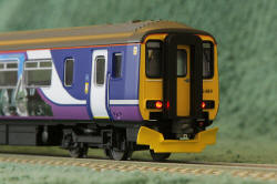
Day running lights are OK (button 0) |
Night running lights are OK (button 1) |
Rear lights work OK (buttons 0 and 1) |
| Completing the trailer car
assembly: Now that correct operation is confirmed, the roof can be carefully clipped back into position. |
| Modification of the power
car: The power car lighting modifications are carried out in a similar manner to the trailer car, except that the presence of the motor requires that the resistors are fitted into a more compressed position within the driving cab, but out of sight below the windows. The power car can be dismantled in a similar manner to the trailer car. |
| Motor and track contact
connections for the power
car: The motor wiring and track contact connections can conveniently be made using the 8 pin NEM 652 connector provided by Hornby on the top of the motor support bracket. |
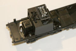
The motor bogie and 8 pin socket with Hornby DC plug
| Removing the RF
suppression capacitor for DCC operation: The small capacitor connected to the motor contacts (see photo below) should be removed for DCC operation. |
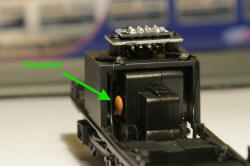
Location of RF suppressor capacitor
| Fitting LEDs to
front-piece: (Identical to trailer car) The headlight and rear light tower LEDs are pressed home until their front face is almost flush with the front of the light housing. The marker lights are mounted to beam at the rear of the clear plastic moulding, directly behind the marker light lenses. (A common anode wire is created for head and rear lights and the anodes of the two marker light LEDs are soldered to this, holding the marker light devices in place. The other leads are trimmed and formed ready to mount the resistors.) |

LEDs inserted into the upper body shell front
| Adding current control resistors: The resistors (as shown in the circuit diagram above) are mounted within the lower driving cab on the power car, taking great care to avoid short circuits and any risk of contact with the motor bogie. The circuitry is kept hidden from direct view through the driver's windows. Attachment points are built in for the decoder cables. |
Resistors squeezed into the front compartment
| Mounting the power car
decoder: The MC4 power car decoder can be mounted in the roof section behind the motor. However, the lack of head height means that fixing is via tape rather than the usual adhesive foam pad. The lighting wires are routed through the roof cavity and down into the front corners of the cab. Blue tack is used to route the wires away from roof clipping apertures. The motor connections and track pick-up wires are connected using Hornby's 8 pin socket, using an NEM 652 plug wired directly to the appropriate 4 wires of the decoder harness. After filing the chassis front upper lip, to fit around the LED bodies, the upper body shell is re-attached to the chassis unit. |
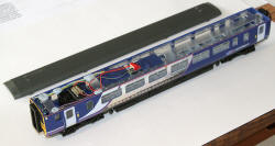 Power car before the roof is refitted |
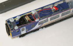 Close up showing the MC4 decoder and wiring |
| Completing the power car
assembly: The decoder is programmed and the whole car operationally tested. All was O.K. except for the car direction, which was the opposite of that expected. The orange and grey wires on the NEM 652 connector were therefore transposed. The roof needed a little local relief with a needle file on some internal webbing to avoid the decoder wiring. Then the roof was clipped back into place. |
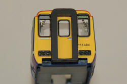
| Updates to the external
appearance of the cars: Northern rail Class 156 units are all now fitted with an "obstacle deflector plate" at each end of the pairs. These were constructed using plasticard and glued on to the front of each car. Both yellow and dark grey units were found on photographs. Yellow was chosen for these cars. Photographs also revealed that the BSI couplers had a considerable impact on the appearance, so these were also fabricated from plasticard and glued in place. Some evidence of underslung equipment was found, between the forward bogie and the front of the car. The exact shape could not be defined so an attempt at representative side pieces was made. |
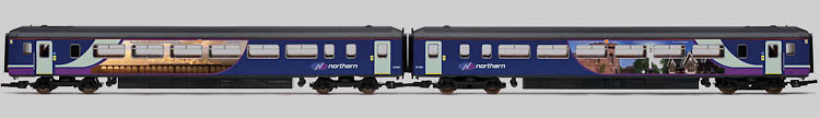
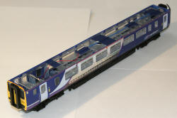
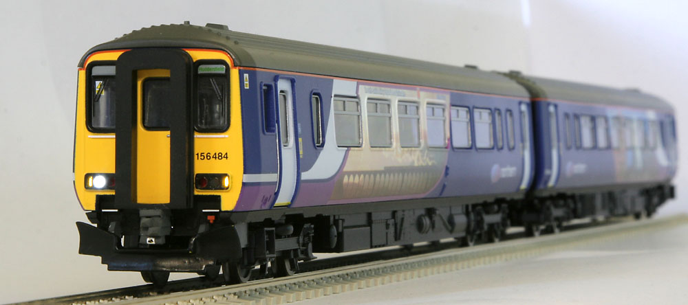
 Completed Power Car |
 Completed trailer car |
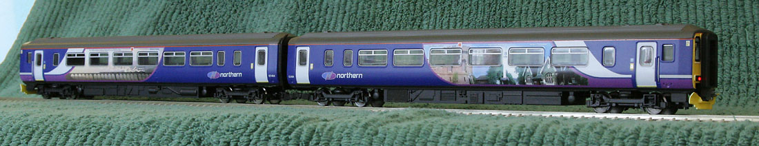
The completed Class 156 twin car unit
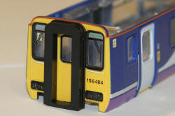
| Subsequent adjustments: Further visits to Leeds and York suggest that the obstacle deflectors of Northern Rail DMUs with the latest purple, blue and white livery, with curved interfaces between the colour bands, are no longer painted yellow. Instead, they start life painted in semi-gloss black, but this soon degrades to a matt grey-brown shade after a few months in service. The model deflectors have therefore been repainted as newly turned out semi-gloss black units. |
Updated deflector colours
| Supplier website links:
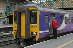
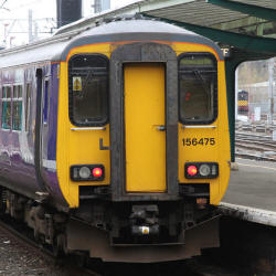
The photos of real class 156s were taken at Carlisle during June 2009. The photos of the model were taken hand held on the kitchen worktop at 1600 ISO with occasional fill-in flash. |