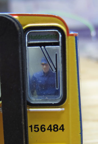
(This Class 156 unit already has day and night running lights plus a front deflector, fitted)
Click on the image on the right for a larger picture

|
Adding sound, internal
lighting & hazard lights to the Hornby Class 156 two-car DMU. (This Class 156 unit already has day and night running lights plus a front deflector, fitted)
Click on the image on the right for a larger picture |
|
Please be aware that this webpage is now over 10years old.
Many of the parts described below are no longer available.
However in most cases better solutions can now be sourced.
|
Introduction: This project uses the running lights equipped Northern Rail "Settle-Carlisle" Class 156 as its starting point. A sound decoder and speaker system, internal lights within the passenger compartment and external hazard lights will be added to the cars. |
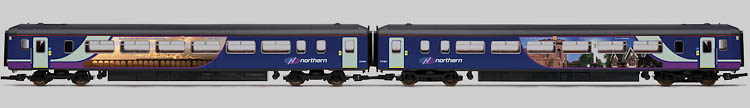
Hornby sales pic. of the original Settle-Carlisle 156 pair
| A summary of the planned
changes: The plan is to replace the current power car decoder with a 21 pin Howes LokSound V4 decoder with adapter pcb (providing 6 function outputs). In the trailer car, the existing decoder will be replaced by a 6 function Lockpilot FX decoder. A large base reflex 4 ohm speaker will be fitted in the below-floor-moulding of the trailer car, connected to the front car via a two way miniature connector. (This enables the power car to retain the traction enhancing ballast weight situated in the corresponding position.) The internal lighting will use 4 or 6 pure white chip LEDs per car, beaming up towards a white painted roof underside, to spread the light evenly. These LEDs will be powered by an anti-flicker "stay alive" circuit in the trailer car. In the power car, stay alive capacitors will be fitted to the entire decoder. Surface mount amber LEDs will be fitted in holes drilled through the painted-on hazard light locations half way along the car sides just below roof level. (These lights come on whenever the doors of the car concerned, are open.) The existing single sided electrical pick ups on the trailer car will be enhanced to provide pick-ups on all 8 wheels. The lighting control will be via button 0 for day running lights, button 4 for the hazard lights, button 11 for night running lights, button 12 for the internal passenger compartment lighting and button 14 for the power car cab light. The sound functions on the Howes decoder will be re-mapped as necessary to achieve this arrangement. I've ordered up some "sitting passengers" and if all goes well, I'll populate the passenger compartment with some of these. I'll also install a scale driver in the power car, if there is room to add a rear cab wall in front of the pivoting motor housing. |

The starting point
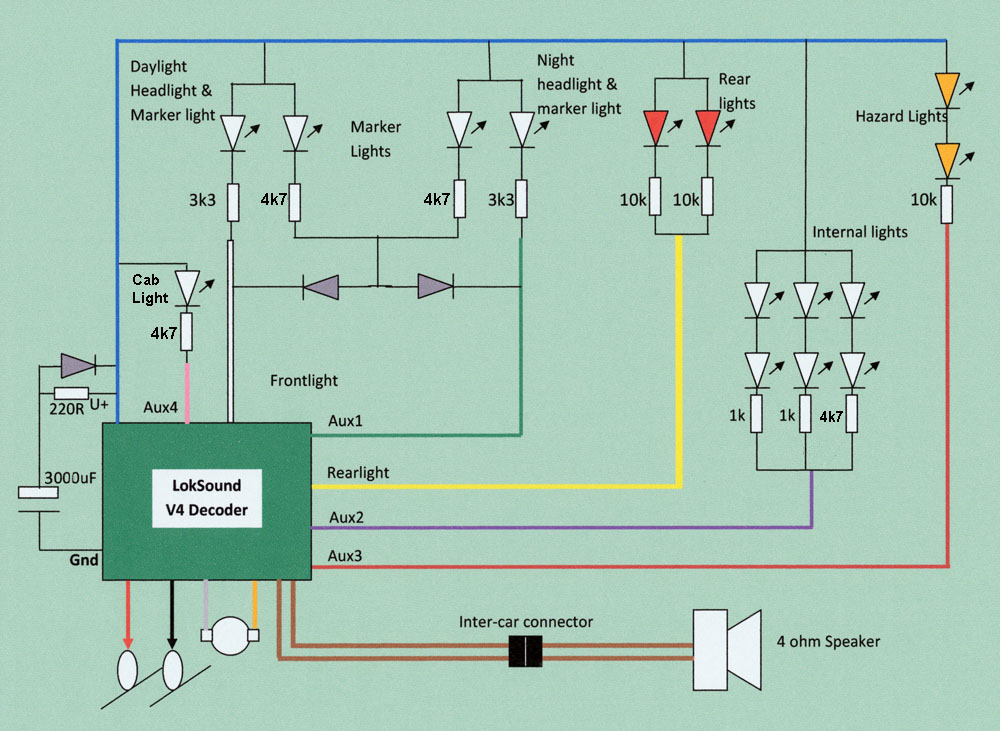
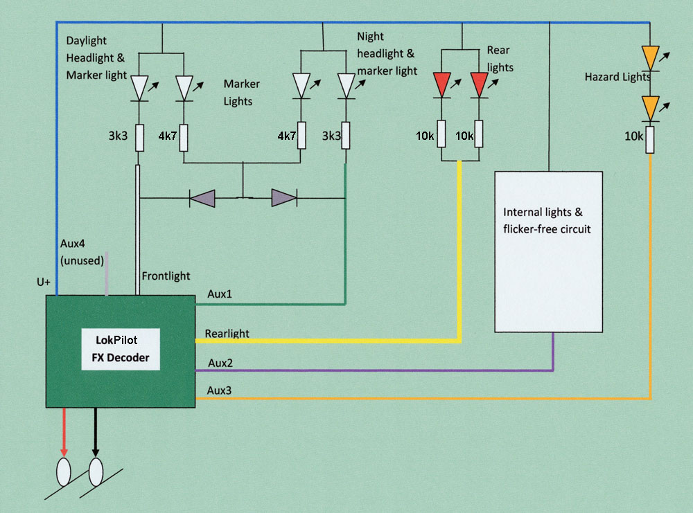
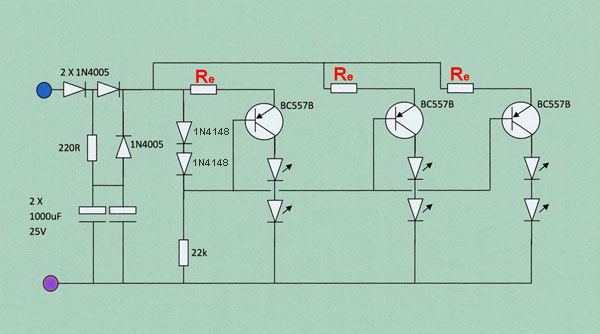
| Circuit Diagrams: Power Car Circuit
Trailer Car Circuit
"Stay Alive / Flicker Free" Circuit for Trailer car Internal Lighting
The trailer car circuit above has been updated to cover a modified lighting arrangement with the LEDs facing downwards & requiring circa 4.5mA of current |
| Preferred LokSound
Function mapping:
|
O.K. That's the plan..... Lets make a start:
| The
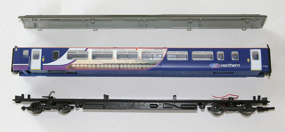
Construction of the cars (trailer car is illustrated
below): First the upper body shell must be separated from the wheeled chassis unit. The lower edges of the sides are carefully prized away from the chassis unit to release the 8 plastic clips holding the two parts together. This is not an easy operation! The roof can then be removed from the upper body shell by releasing the eight clips holding these two parts together. (See picture below for the location of the clips.)
|
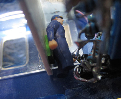
| Fitting a driver in the
power car cab: There is just room in front of the pivoting motor bogie, to insert a rear cab wall (1mm plasti-card). The front lighting series resistors don't leave a lot of space for much more than a Northern Rail driver and his seat back. An additional LED will be fitted above the driver, activated by the LokSound decoder output, Aux4, via button 14.
|
| A convenient location is
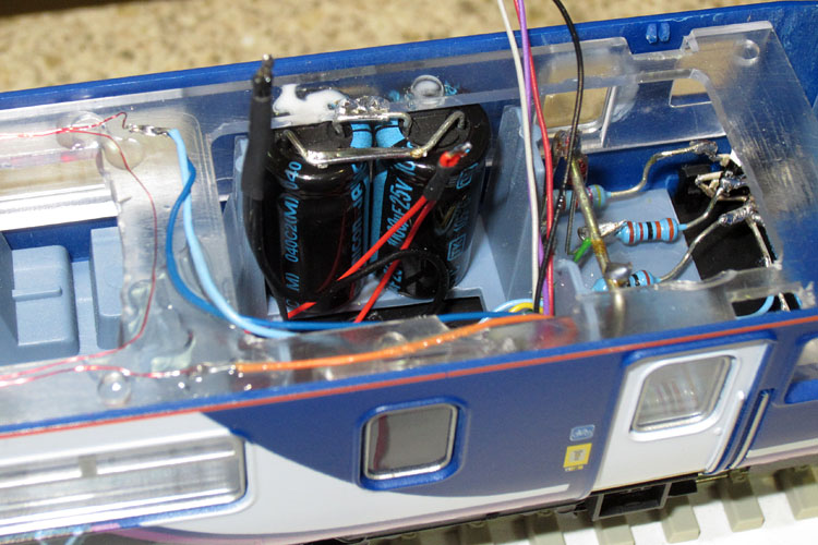
identified for the large "Stay Alive" capacitors: There is room to fit three 1000uF 25V electrolytic capacitors, beside the ballast weight in the power car chassis assembly. The weight had to be shifted a few mm towards the rear in order to make enough space to fit two of the capacitors side by side. The capacitor leads are connected in parallel and connect to the upper body, using spare ways in the 8 pin NMRA plug and socket. The capacitors are held in place by pieces of Blu Tack.
The underside detail maybe a bit lacking, but at least there's room for the capacitors
The 3 capacitors are wired in parallel and connected to two spare sockets on the 8 way NMRA connector. |
| Hazard lights: A rectangular hole is cut through the plastic body shell in the centre of the orange square. (Using first a drill, then a needle file). The amber LED leads are run through the hole and a very small blob of Blu Tack is used to hold the rear of the LED in the correct position, while clear adhesive is applied over the outside surface of the LED and the edges of the aperture. When the clear adhesive is completely dry, orange water colour paint is applied over the lens of the new hazard lights.
|
| Power Car LokSound
Programming to remap the buttons First the sound slot numbers are found by interrogating the 3 CVs assigned to each sound trigger button (click here to see the chart I use for this job). The sound slot numbers appear in column 3 below.
CV Changes Required:
|
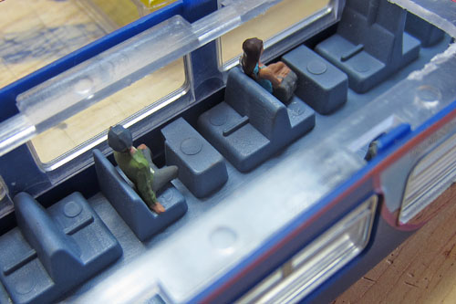
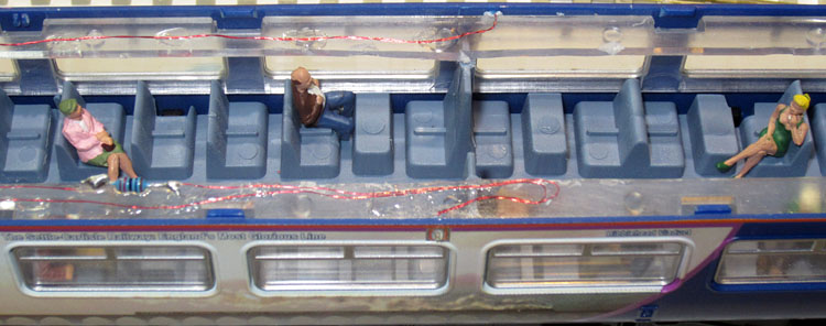
Adding A Few Passengers:
The central glazed roof sections have been partially removed to improve access and (hopefully) to improve the internal lighting. The figures are from the Noch HO range. Hopefully the unusual clothing contrasts will not be so obvious when viewed through the finished train windows. |
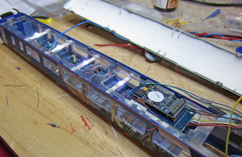
| Fitting the Interior
Lights:
White LEDs on cross-beams facing up towards the white painted roof, plus another pair facing downwards below the decoder (The decoder & adapter PCB are not connected & have just been put in place to test the lighting)
The lighting effect when the roof is temporarily placed over the car
Although the use of LED light bounced off the white painted coach ceiling, gives a well distributed even lighting effect, the two LEDs pointing downwards from under the decoder PCB, create a brighter effect (Or draw much less current in generating a similar light level.) |
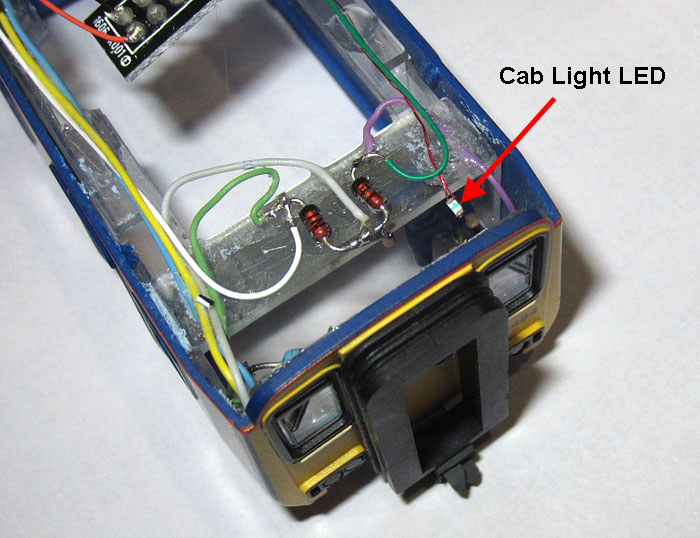
| Adding the Cab light LED: The cab light is simply a chip LED hanging on its leads in the top of the cab. The chip has been deliberately tilted down at the front to minimise light escaping directly through the windscreen.
ESU Adapter board wired in |
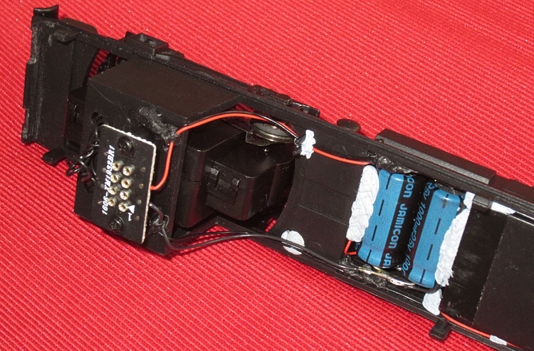
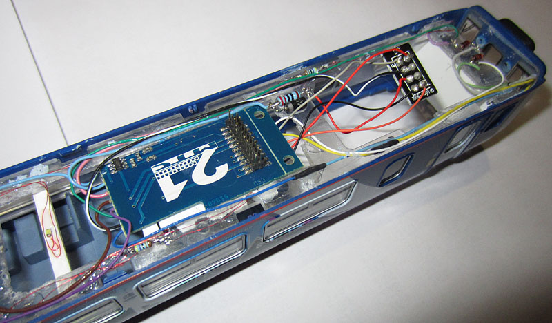
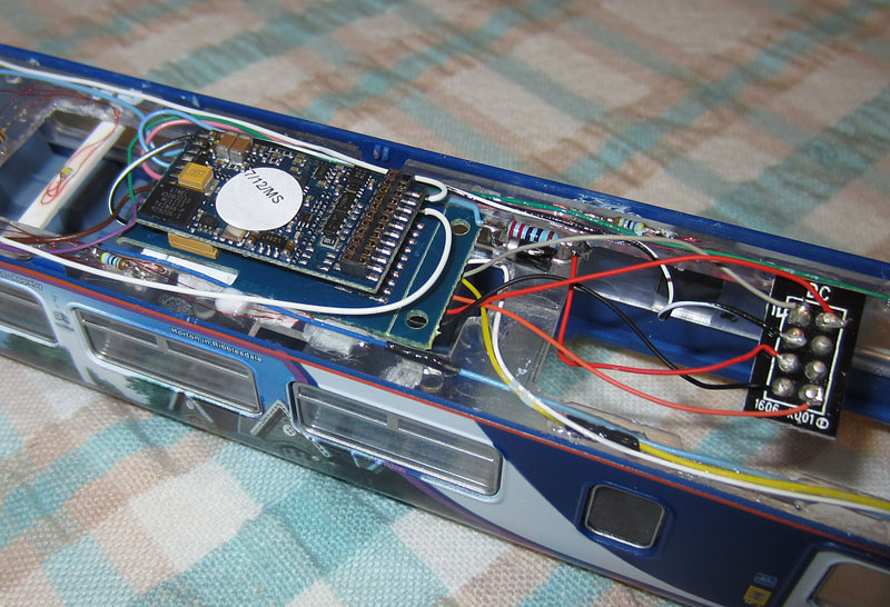
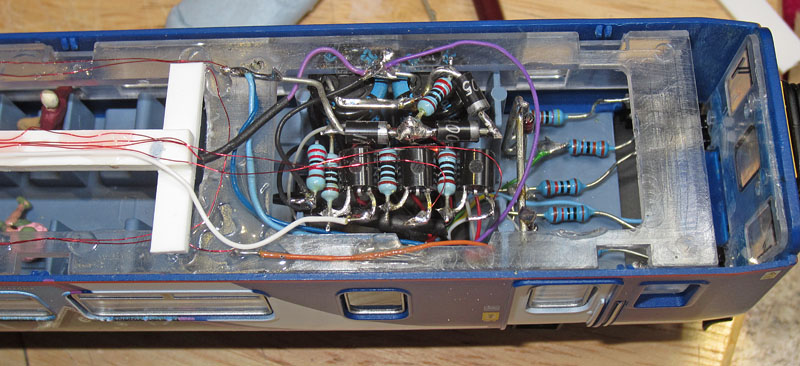
| Fitting the Decoder
adapter board: ESU supply an adapter PCB that provides wired access to the 21 pin decoder connections. The adapter board also includes amplifiers for the two additional LokSound function outputs, with minimal current switching capability. Also, easy access to the ground connection is provided (required for stay-alive capacitor connection). On the 156, the adapter board is mounted so that its top surface is level with the top of the internal glazing moulding. This leaves just enough room below the roof for the decoder to fit. The additional ground, V+, Aux3 and Aux4 wiring was first added, then with the adapter board lightly glued in place, all the wiring was trimmed, routed and soldered in place. (held down with clear adhesive). The track connections, motor wires and stay-alive capacitor wires were connected to the 8 pin NMRA plug, ready to provide the interconnect between the upper body assembly and the chassis.
ESU Adapter board wired in |
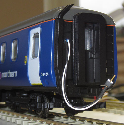
| Adding the Power Car
speaker socket: The speaker is mounted in the trailer car so that the ballast weight in the lower body housing of the power car can be retained. A miniature TCS twin socket is super glued to the end of the car, with the leads passing through two small holes drilled in the end wall.
The speaker socket glued in place before it's connected up. |
| Fitting the decoder and
completing the wiring:
The decoder in place, plugged into the adapter board. The speaker wires are taken directly from the decoder for higher reliability and slightly less resistance.
The wiring is fitted above the glazing moulding, with care taken to leave the roof clip apertures clear of obstructions.
Oops! It works much better when an 8 pin plug is used instead of a DCC ready DC-blanking-plug with shorting links built in! |
| Optimising the motor
control CVs:
156 on the test track with temporary piggyback speaker connected to the rear socket. Initial results with defaults were disastrous, so I immediately ran the auto-optimisation routine by setting CV54 to zero and running the loco down a straight test track by pressing F1. However, although the resultant performance was better than with the defaults, movement using the lowest two speed steps was still very jerky. By experimental optimisation of the CVs, one at a time, I achieved smooth running on all except the first speed step. Reading the details in the manual gave a few more clues and I eventually homed in on a smooth solution even for speed step 1. However, a slight and variable tendency for jitter still occurs when moving between speed steps one and two (in either direction). This maybe due to mechanical issues, but the effect is fortunately not too obvious, particularly under computer control.
|
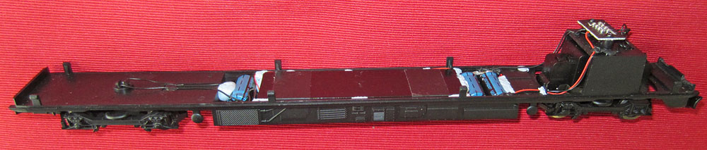
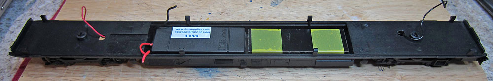
| Next, the trailer
car....... Fitting the speaker and a new ballast weight to the chassis: The original trailer car ballast weight (52gm) obstructs the speaker location. This was therefore removed and holes were cut in the chassis underside to correspond with the cone and base port of the new speaker. A new ballast weight was trimmed to fit beside the speaker (58gm this time). The speaker was super-glued to the chassis base and the new ballast weight was held in place using double sided foam tape.
Chassis top view showing the speaker & ballast weight
Underside view showing the speaker apertures
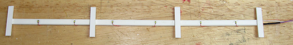
Adding wheel contacts to the unmodified half of each bogie: Additional wheel wiping contacts were added to each bogie, using 1mm wide phosphor bronze strip. The wipers are pre-formed and then fixed in place using superglue at the mounting point near the centre of the strip, where a plasti-card block clamps the strip to the bogie centre plate. A wire will be soldered to the strip when the glue has dried.
Additional wheel-wiper strip added (towards the top of the photo)..... Those wheels need a clean! |
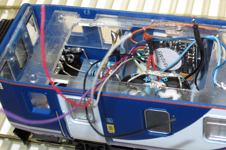
| Trailer Car
Decoder and Stay-alive capacitor locations Decoder: The area in the trailer car corresponding to the motor location in the power car has blanked off windows, making it an ideal electronics bay. The decoder is mounted using double sided tape on the side of the car.
Near the cab end of the trailer car, showing the decoder. Capacitor Location:
Opposite the decoder is space for two 1000uF 25Vcapacitors
Adding a few passengers: More of the Noch seated passengers were glued to appropriate seats.
Passengers added. (The wiring visible in the above photos is associated with the hazard lights). |
| Trying direct illumination
in the trailer car instead of bouncing the LED light off the ceiling: The lower current required by the two front cabin LEDs below the decoder in the power car, would suggest that as long there are enough LEDs to give a reasonably even light level, then fitting LEDs in the roof, beaming downwards should give a significant improvement in lighting efficiency. Doing some simple sums, alternative emitter resistor values for the constant current sources in the anti-flicker circuit should result in the reduced LED current values indicated in the table below. I will have to experiment to get the overall light level similar to that of the power car. Have to pop over to Maplin tomorrow to get some more low value resistors!
Showing the resistors that determine the LED brightness in red (Re) Running the downward facing LED solution using temporary series resistors, a current of 4.5mA through each LED gave a similar light level to the upward LEDs in the power car, so if I build with 100 ohm emitter resistors, results should be about right. Re = 100 ohms
Interior lights and flicker-free circuit added
The underside of the lighting assembly, showing the downward facing LEDs
Close-up of the anti-flicker circuit, located in the top of the electronics bay.
Speaker 2 pin plug and cable |
| Programming the Trailer
Car LokPilot FX decoder: The CVs need to be adjusted to switch the appropriate lights using the same lighting buttons as the power car:
All lights now working as planned! |
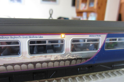
| Final optimisation: The relative sound levels need some adjustment...... e.g. a drop in engine sound level compared to the horn sound level.
Also, the rear lights are a bit too bright and these need toning down a little. Easier at this stage to use the decoder software than to change the series resistors!
The speaker cables can be seen where they emerge into the passenger compartment. Soon resolved with the use of appropriate paint. |
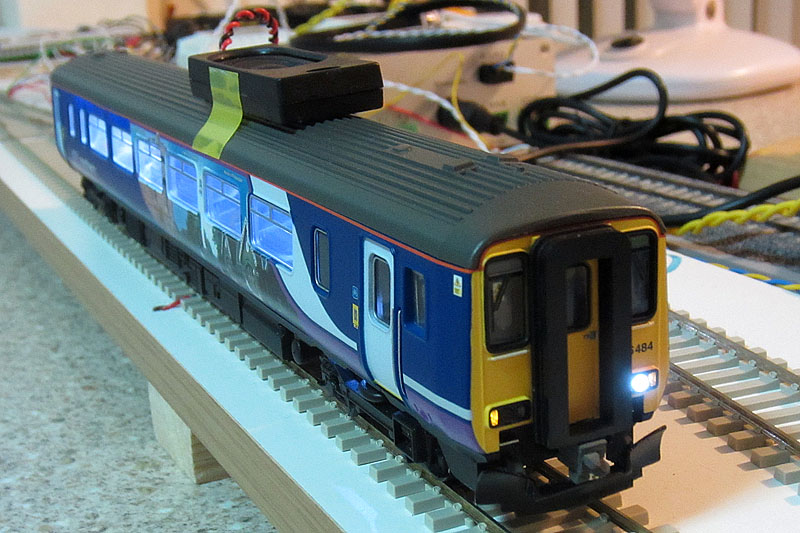
Finally some night running images on the test track, prior to computer schedule optimisation

Power Car
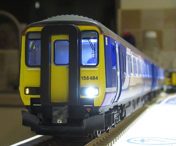
Front view

Rear Car (with speaker cable just visible)
To watch a YouTube video demonstrating the sound on the test track, please click here
| Supplier website links:
The photos of real class 156s were taken at Carlisle during June 2009. The photos of the model were taken hand held on the kitchen worktop using a Canon Ixus 220HS. |