DCC conversion and Lighting update of the Bachmann Class 170 3 car DMU.
|
DCC conversion and Lighting update of the Bachmann Class 170 3 car DMU. |
|
|
Introduction: This document provides a summary of the process adopted to incorporate DCC decoders and correctly operating external LED lighting in the Cross Country Trains variant of the Bachmann 3-car Class 170 unit (OO gauge). Note that the smaller pictures can be enlarged by clicking on the image. |

| DCC Conversion Approach: The plan is to use a 2 function and back emf motor controller TCS T1 decoder in the centre power car and a 4 function TCS FL4 (function only) decoder in the leading and trailing unpowered cars. To provide correct operation of day and night running lights on the end cars, 4 function outputs are required. External Lighting Modifications: The Bachmann model includes bulb lighting which illuminates the external light lenses via plastic light pipes. The original lights provide correct daylight operation, but draw enough current to run hot, and hence risk future reliability problems. It is planned to replace the bulbs with LED devices. The forward headlight and side marker light-pipe assembly will be removed, and all the lower forward lights will be changed to individual LEDs. The rear light-pipe and top marker light-pipe will be retained, illuminated by new LED devices. The DCC decoder programming will be arranged to handle correct day and night running of the lights via function buttons 0 and 1 respectively. (For day running, right hand headlight, left hand and top marker lights in the forward car plus both rear lights in the rear car. For night running, left hand headlight, right hand and top marker lights in the forward car plus both rear lights in the rear car. |
|
Day running Lights |
Rear Lights |
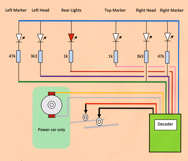
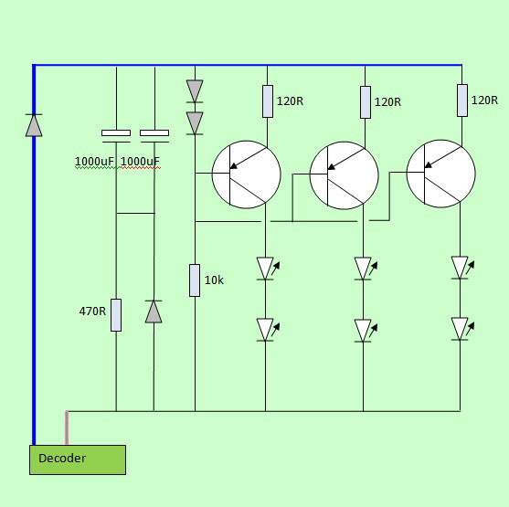
| Circuit Diagram for
lighting and power car connections:
In the power car, only the motor (orange and grey wires) and track (red and black wires) are connected. In the end cars, only the track and lighting connections are used (red/black, green, purple, brown, pink and blue wires). The resistors control the current flowing through each LED. This determines the intensity of the light generated by the LED. The values were established by experiment, for the LED types employed. Some adjustment may be required if different LED types are used or if light level refinements are thought necessary. |
| Achieving Access to the
trailer cars: First the upper body shell must be separated from the wheeled chassis unit. The two screws in the chassis unit near either end of the car must first be removed. Next the lower edges of the sides are gently eased outwards to release the 4 plastic clips near the centre of the car, allowing the two assemblies to be eased apart. The electrical connector in the wiring between the two assemblies can then be separated. (The flying lead connector wires are removed from the PCB in the chassis unit as it is planned to directly solder the decoder leads to this PCB.) The roof can be removed by releasing the clips holding it to the side walls. |
| Access to the Lighting PCB
Assembly: Bachmann have contrived to make the removal of the bulb lighting assembly, a real problem, by screwing this to the car centre wall, before gluing upper body shell parts of the car together. To remove the original lights, disassembly of the car in one form or another is required. On the example I have, the bonding of the car front piece to the sides was sufficiently weak to allow separation of the front-piece from the rest of the unit with only slight collateral damage to one car. (However I am advised that this is not always the situation, so other strategies will be required on some 170 units!) The screws holding the lighting PCB and the lower light housing to the car front-piece can then be removed and after cutting the bulb wires, the original bulb lighting can be removed from the front-piece. The rear light-pipe and top light-pipe clear plastic mouldings are left in place, while the combined front head and marker light-pipe is removed. The clear plastic bungs mounted in the left headlight and right marker light locations must also be removed. |
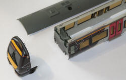 Car front-piece and roof separated from the sidewalls.
|
|
 Car-front piece |
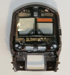 Car front-piece from behind |
| Fitting the new LEDs: The replacement LEDs are white 2mm tower types available from specialist suppliers such as DCC Supplies and/or Bromsgrove Models (see end of article for website links). A 2mm twist drill was run through the marker light holes to ensure a good fit. The new LEDs should be a tight fit and when wired together with their resistors, will be robust enough not to require a PCB. |
| Eliminating "Light bleed"
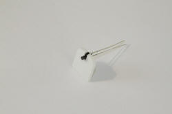
between the new LEDs: Light from the LEDs will couple into adjacent devices if fitted straight out of the bag, producing a very unrealistic effect. To prevent this, the LEDs are painted with gloss black modelling enamel, leaving just the outer face of the 2mm diameter tower exposed. I now also paint a white dot on the negative side of the LED body (shortest lead) before use, to avoid later wiring errors. Once the LED leads are trimmed, its easy to forget the polarity! |
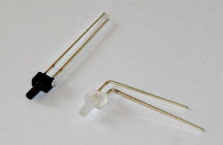
Black painted LED beside "as delivered"
| Fitting LEDs to
front-piece: The headlight and marker light tower LEDs are pressed home until their front face is almost flush with the front-piece surface. The inside of the front windscreen is protected from damage using a piece of kitchen roll taped in place. The common anodes of each light cluster are soldered together and the other leads are trimmed and formed ready to mount the resistors. |
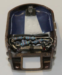
Front LEDs and resistors installed
| Adding current control resistors: The resistors (as shown in the circuit diagram above) are mounted in the form of a classic "rat's nest", taking great care to avoid short circuits. The circuitry is kept hidden from direct view through the driver's windows. Attachment points are built in for the decoder cables. |
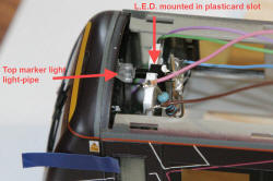
| Fitting Rear Light and top
marker LEDs to
the upper body: The rear light LED is mounted in a slot cut out of the bottom of the forward internal wall, immediately behind the light-pipe. When the front-piece is relocated, this LED should beam directly into the rear light-pipe. For the front top marker light, a piece of 2mm plasticard is cut out, with a slot in the top, sized to provide a tight fit for the LED. The plastcard is then glued to the front face of the rear of the two internal walls attached to the front of the car side walls. The plasticard is positioned so that the mounted LED points directly at the top light-pipe. The resistors associated with the rear and top lights are soldered in series with each LED and are mounted, taking great care to avoid short circuits. The circuitry is kept hidden from direct view through the driver's windows. Attachment points are built in for the decoder cables. |
 Rear light LED fitted in place
|
 Top marker light LED in plasticard slot
|
 Rear lights (red) LED switched on, showing LED beaming at light pipe |
 Top marker light LED showing the LED beaming into the light pipe |
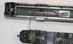
| Connect the FL4 decoder: Connect the appropriate decoder wires (as shown in the circuit diagram) to the front-piece assembly. Route the decoder wires above the front wall in the upper body shell and along the underside of the roof. Offer up the front-piece to the upper body shell and tape in position. Connect the red and black decoder wires to the small PCB on the lower chassis unit. Use the PCB track pads which already terminate the chassis wheel contact red and black wires. Then place the chassis unit on a test track to programme the decoder and test the lighting operation under DCC function button control. |

Test track arrangements
| Programming the CVs: Using the DCC controller (mine is a Bachmann Dynamis) the trailing car FL4 CV values were programmed into the decoder.
The "rule 17" dimming option provided in the TCS decoders has been used, so that when the train is stationary, the headlights and marker lights are dimmed. As soon as the train is made to move, these lights come up to their normal intensity. |
||||||||||||||||||||||||||||||||||||||||||||||||||||||||||||||||||||||||||||||||||||||||||
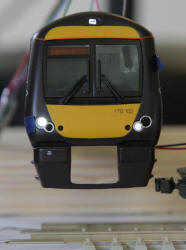
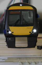
| Testing the Lights: Button 0 should activate the day running lights (right hand headlight with left hand marker light in the forward direction for this car and both rear lights in reverse). Button 1 should activate the night running lights (left hand headlight with right hand marker light in the forward direction for this car and both rear lights in reverse). |
|
Day running lights are OK (button 0) |
Night running lights are OK (button 1) |
Rear lights work OK (buttons 0 and 1) |
| Completing the end car
assembly: Now that correct operation is confirmed, re-fit the roof and attach the decoder to the roof underside with an adhesive foam pad. The decoder wires can be tidied and taped to the underside of the roof and the front-piece can be glued back to the upper body shell. The upper body shell can finally be clipped and then screwed to the chassis unit. This completes the trailer car modifications. The leading end car updates are similar except for the opposite direction cv programming, which is shown in the cv tables above. |
Decoder fixed, ready for taping the wires down and re-assembly
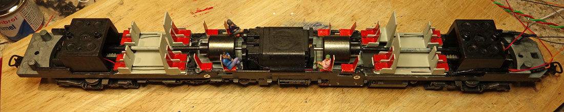
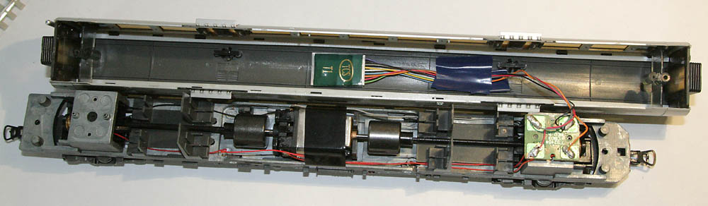
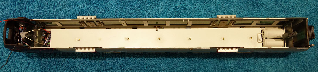
| Modification of the power
car: The modifications to the power car concern the motor wiring, which must be changed for DCC operation. Separate the upper body shell from the metal framed chassis in the same way as already carried out to the trailer cars. Remove all the small capacitors and the two ferrite cored coils from the small PCB mounted above one of the bogies. Leave the motor and wheel connection wire terminations on the PCB in place. |
PCB above the bogie, with coils and capacitors removed
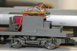
| Mounting the power car
decoder: The larger power car T1 decoder is mounted in the same manner as the trailer car decoder, fitted to an adhesive foam pad in the roof of the upper body shell. The decoder red and black track pick-up wires and the decoder orange and grey motor leads, are then soldered to the appropriate pads of the chassis PCB. The chassis unit is then placed on the test track for programming (see the power car CVs in the above table). After an operational test, the decoder wires are tidied by taping them to the upper body shell roof. The length of the wires between the decoder and the chassis PCB may need adjustment to minimise the appearance of the cables through the side windows, when the upper body shell is re-attached to the chassis unit. |
Decoder in place and wiring tidied
| Completing the power car
assembly: With correct operation confirmed, and the decoder wires tidied and taped as required, the upper body shell can be clipped and then screwed to the chassis unit. This completes the power car modifications. When the desired train address has been chosen, programme the same address individually into each car, sequentially, on the test track. Then place all 3 cars on the maintrack, couple up and verify that operation is as expected.
|

The completed 3 car unit
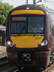
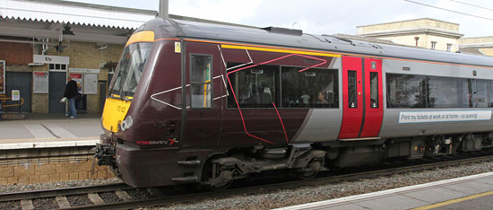
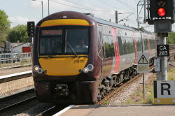
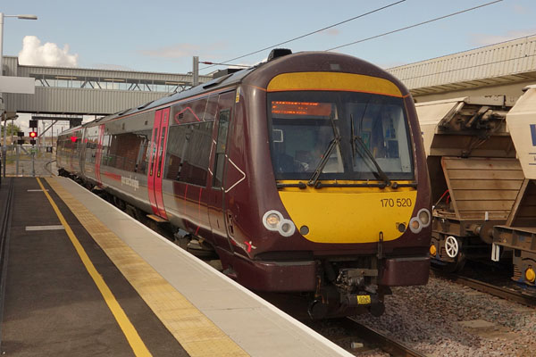 The Stansted Airport Class 170 arrives at peterborough station |
Its Upgrade Time........ |
| Thoughts for a further
upgrade: I see these trains on Stansted airport duty at Ely station regularly and I think its time I considered an upgrade to include a sound system, door hazard lights (perhaps with independent rear car switching for the guard?) and internal lights. Also a driver and some repainting of the internal seats & floor, with a few passengers to complete the job. Its quite a long train, so a speaker in each end car has some attractions. I've had a check on You Tube for sound project availabilty and so far I've found Legomanbiffo, Olivias Trains and Coastal DCC examples demonstrated. I plan to give the Coastal variant a try, which seems to have a very familiar idling sound. Pity its not realistic to expect the low frequency content of the MTU power units to be generated from 20x40mm speakers, they really let you know they are there at station departures!
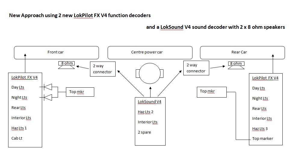
The comprehensive function mapping properties of the new LokPilot FX V4 function decoders, give full lighting control flexibility. There is room for 20x40mm speakers in the end cars, but not in the centre car, so 2 way miniature connectors will feed the decoder output between the cars. The two 8 ohm speakers will be connected in parallel to present a 4 ohm load to the decoder.
Bits List... All sourced from Coastal DCC ..... good prices and useful advice from Kevin! LokSound V4 with Coastal 170 sound project 21 pin 2 x LokPilot FX V4 21 pin decoders 3 x ESU 21 pin adapter board (without buffer amps) 2 x Two way TCS connector 2 x ABS Speakers (40 x 20mm 8 ohms) Diodes, we have plenty Internal Lights: 3 x Daylight white nanolight 6 pack Hazard lights: Amber nanolights 6 pack
|
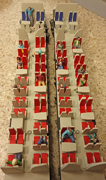
| Some cosmetic updates to
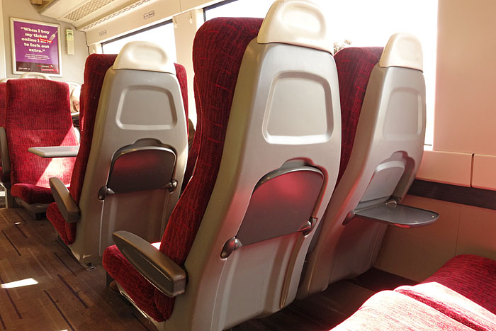
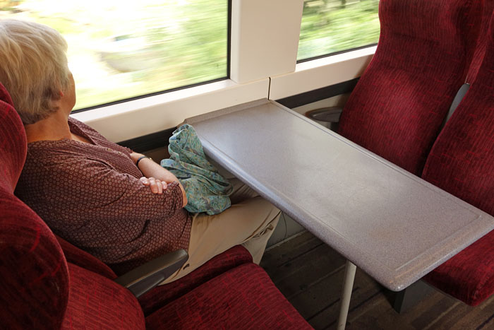
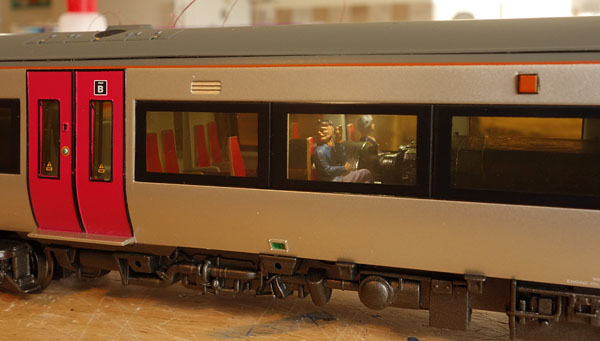
the passenger seating: A brief trip from Ely to Peterborough on a Cross Country 3 car set (Aug 2014) confirms that the seats, tables and flooring are not really black overall.....
Central area in centre car. (No sign of that big Bachmann electric motor either! :-)
Mottled grey table tops ("No...... I deny any knowledge of the strange gent taking photos in the coach!")
In fact all the seats were red, but I'd already included blue ones at the ends, based on Cross Country Voyagers from a couple of years ago.... |
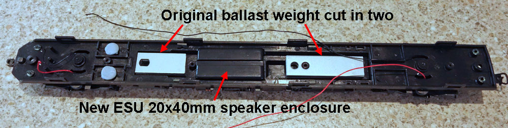
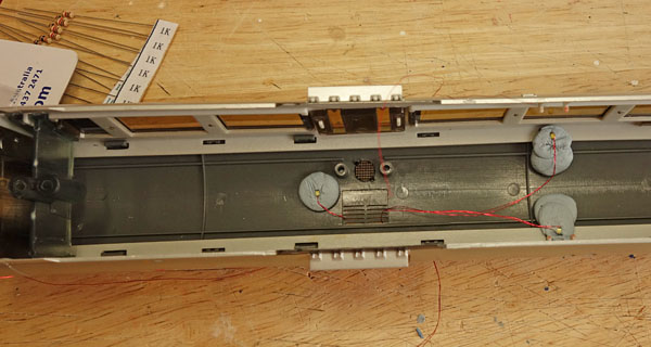
| Fitting a 20x40mm speaker
in the end cars: I have several spare unused ESU 20x40mm speaker enclosures. These provide a simple way to mount the new 8 ohm 20x40mm speaker. The location is a little forward of centre, to avoid having to cut into the protruding motor moulding. The side mouldings fitted to the car underside can be removed, to simplify the task of hacking a 22x42mm rectangle of plastic from the bottom of the main underside moulding, to accommodate the new enclosure. The steel ballast weight is first removed. This weight can be re-fitted (using super glue) on either side of the speaker enclosure when cut into two (unequal length) pieces.
Showing the new speaker enclosure and original ballast weight repositioned, after a bit of work with the hack saw.
Wiring (including speaker wires) now glued in place and extended where necessary.
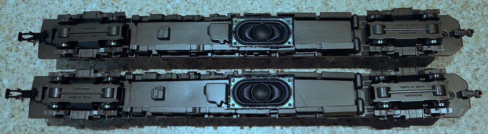
and then.......there were two! |
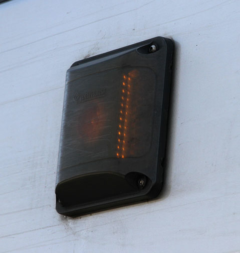
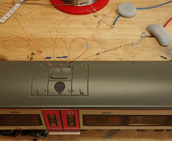
| Illuminating the door
hazard lights: The Bachmann's 170 hazard lights are formed using a separate translucent moulding for the lens, which protrudes through a square aperture in the body side mouldings. Opaque Orange paint is applied to the outer surface of the lens moulding. In fact the real lights are Dewhurst PA51 status indicators, predominantly black in colour, with a small circular matrix of orange LEDs beaming out at 90 degrees to the side of the car and vertical rows of orange LEDs, beaming forward and backwards along the car sides. The last two LED groups are angled in such a way as to maximise illumination along the length of the train, so that the guard can see if they are on, when leaning out of the rear cab window or any of the train doors. (To check that the doors are closed.) The orange light is not very bright when viewed in daylight.
Photos of a real door hazard light on a Cross Country Class 170 at Ely station
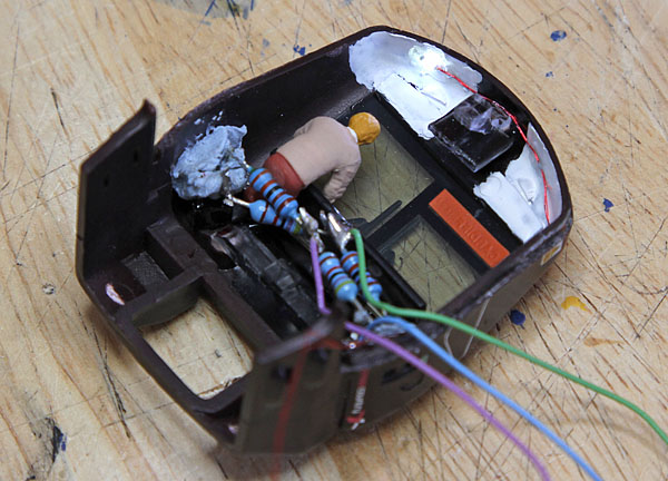
My compromise involves scraping off the original paint from the lens moulding and opening out the hole in the rear of the lens moulding. First a 1.5mm drill is used to remove material, stopping just short of the front face. Then a 2mm drill is used to open up a wider hole somewhat shallower, to accommodate an amber nanolight LED, which is glued in place. The thin material in the centre of the lens results in a circular central bright region, while the amber light also diffuses out of the edges. A thin matt black line is painted around the base of the lens, when in situ, also covering the extreme top and bottom of the lens.
I've set the LED current to give a slightly brighter light than on the real train as I want it to be clearly visible when switched on. |
| Adding a driver and cab
light: A Noch driver with lowered right arm has a rather uncomfortable ride, glued to one of the original leaded resistors in the cab. Illumination is provided by a daylight white nanolight LED, glued to the white painted inner cab roof. I tried illuminating the destination board too, but its nearly opaque and the effect was not at all satisfactory.
|
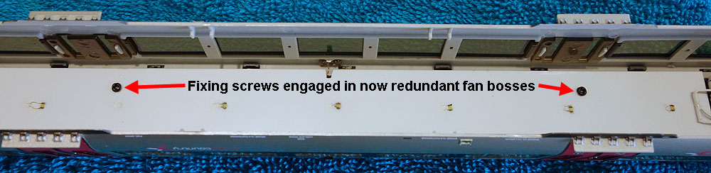
| Fitting an inner roof and
the function decoders in the end cars: Bachmann's 170 separate roof construction technique, presents a threat of light leakage between roof and sides when the internal lights are on, so a plasticard inner roof is fitted just below the join to prevent this. The inner roof is held in place using screws, self tapped into the original fan fixing bosses, so that it can be removed if necessary. The interior lighting LEDs are glued to the inner roof underside, with their wiring hidden in the new roof cavity. The roof grills and fan ports also present a light leakage risk, but as the fans can't easily be seen, I've removed them, to simplify the inner roof construction. Localised black paint, applied on top of the inner roof below these openings, should prevent internal light escaping by this route. I had originally planned to use 21 pin LokPilot FX function decoders mounted on adapter boards. But if roof mounted, these would require holes cutting in the inner roof due to the combined head height. However, fortunately I have a pair of identical leaded decoders of the same type, obtained previously for another project and these will fit between inner and outer roof without any further surgery, so, I've used these instead. (Deferring the 21 pin devices for future projects.... perhaps 150 or 158?). |
| Lead & rear car LokPilot FX V4
decoder wiring:
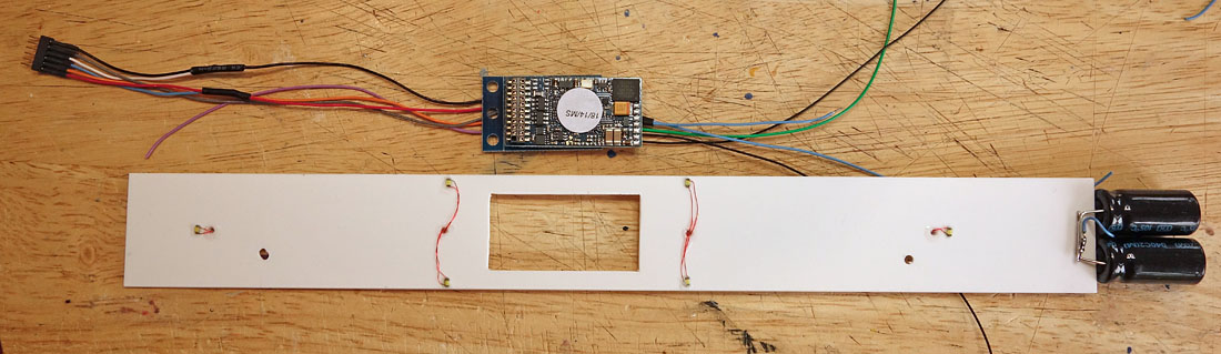
The upper marker light negative supply is via diodes to the Aux 1 and Aux 2 outputs. The internal lights are supplied via a flicker free circuit, supplying circa 5mA to each of 6 white LEDs and backed up using a large capacitor. (See below)
Passenger compartment lighting circuit. The capacitors keep the lights at full intensity for circa one second if the supply is interupted. |
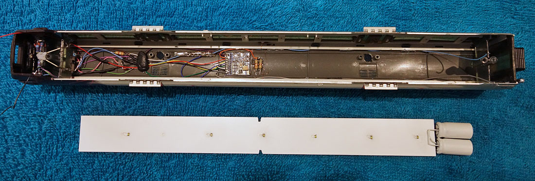
Upper body shell assembly and new inner roof (with the capacitors painted white).

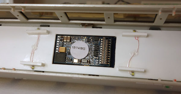
Showing the new LokPilot FX V4 Function decoder wired in.
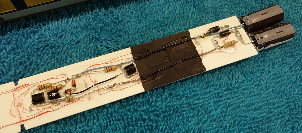
Anti-flicker circuit components on the top side of the inner roof. (The black painted area is under the ventilators.)
Inner roof in place, with interior lighting LEDs visible (with the anti-flicker caps painted white at the rear).
| Revised Function mapping
for the train with Howes 170 scheme:
Programming the Car 1 ESU LokPilot FX V4: (First time on this decoder) I soon discovered that the default CV programming on the V4 version of the LokPilot FX function decoder, is very different to that shown in the manual .....and fortunately the real arrangement is much more useful from that shown in the manual, with only a few CV changes necessary to modify the function mapping in line with the table above! The really useful feature of the V4 version is that the functions can be controlled using any button up to F28 with full directional control. Default programming: Programming line 1 condition is F0 forwards and the output is the white (headlight) logical function. Programming line 2 condition is F0 backwards and the output is the yellow (rearlight) logical function. Programming line 3 condition is F1 both directions and the output is the green (Aux.1) logical function. Programming line 4 condition is F2 both directions and the output is the green (Aux.2) logical function. Programming line 5 condition is F3 both directions and the output is the green (Aux.3) logical function. Programming line 6 condition is F4 both directions and the output is the green (Aux.4) logical function. All the other programming lines CVs seem to be set to zero (based on a small but specific sample).
Changes required for Lead Car: (The individual CV numbers can be found using the ESU manual) Line 1 change output to Aux.1. Line 2 O.K. Line 3 change condition to F10 forwards only; change output to Aux.2. Line 4 change condition to F10 backwards only; change output to Rearlight. Line 5 change condition to F11 both directions. Line 6 change condition to F14 both directions; change output to headlight. Line 7 set condition to F15 both directions; set output to Aux 4. Line 8 set condition to F16 both directions; set output to rearlight. All working fine except that the internal lights are creating an overload. (Oops! I'd connected the grey decoder wire to the wrong side of the capacitor discharge diode!....all now fixed!) Changes required for Rear Car: (The individual CV numbers can be found using the ESU manual) Line 1 change output to rearlight Line 2 change output to Aux 1 & headlight. Line 3 change condition to F10 forwards only; change output to Rearlight. Line 4 change condition to F10 backwards only; change output to Aux 2 & headlight. Line 5 change condition to F13 both directions; change output to Aux 3. Line 6 change condition to F15 both directions; change output to Aux 4. Line 7 set condition to F16 both directions; set output to rearlight. All working fine!
Changes required for Power Car: (Indicated by the blue shading, the individual CV numbers can be found using the ESU manual) Remove shunt mode from F10, Remove zero CV3 & 4 from F11 Remove Aux1 from F12 and add Aux2 instead Remove Aux2 from F13. Add Aux 1 to F15. Add a "when moving only" condition to F9. Inspect the wheel contacts to identify the reason for occasional brown outs and fix it! |
| Button | Function |
| 0 | Day running lights |
| 1 | Engine on/off |
| 2 | 2 tone horn |
| 3 | Reverse 2 tone horn |
| 4 | Single tone horn |
| 5 | Doors open |
| 6 | Right away buzzer |
| 7 | Doors close |
| 8 | Dispatcher whistle |
| 9 | Flange squeal |
| 10 | Night running lights |
| 11 | C-Car Hazards |
| 12 | B-Car Hazards |
| 13 | A-Car Hazards |
| 14 | Cab light |
| 15 | Interior lights |
| 16 | Parking lights (both rears) |
| Lighting the central
car...... without highlighting the motor in the middle or the bogie
mounting towers at the ends: The Bachmann motor arrangement gives good reliable performance, but really compromises the internal appearance of the centre car.
"Before" above and after a bit of work "below"
I've painted the motor and the end towers matt black and I've removed the original Bachmann PCB and wiring from the top of one of the end towers. The wiring has been rerouted along the side of the tower, ready to be routed out of sight up into the end of the upper body shell. I've fabricated some seats from plasticard, which I've arranged beside the flywheels and the plan is to populate some of these and to arrange the roof lights to beam down directly over the few seats in each corner of the central seating area. The other two LEDs will be placed centrally over the door areas, biased slightly towards the single seat rows next to the end towers. If necessary I'll fit small shrouds around the lighting LEDs to confine their beams and as a last resort, I'll make some dummy blinds to place behind the centre and end windows. Those flywheels still look very conspicuous but I'm reluctant to paint then matt black in case I unbalance them! Experimenting with the passenger compartment illumination LED locations:
Half a coach with 3 LEDs
The wires are fed through the roof top vents for the test.
the central LEDs are directly above the passengers.
Hidden side of decoder mounting board (with 21 pin LokSound mounted on the other side) and hidden side of inner roof assembly with anti-flicker circuit
Visible side of both assemblies. (The decoder high points protrude just below roof level, directly above the motor, hence the rectangular hole.)
Showing the decoder in place. (The six pin connector on the left will connect to the motor and track contact wiring from the chassis assembly.) |
Adding a few more passengers to the end cars.
| The Sound Project: The original Coastal sound project was pretty good, with a particularly convincing engine idle sound. However, the dynamic engine sounds were a bit lacking compared to Bryan's typical Howes offerings, so I finally decided to reblow the sound project. The Howes engine idle sound is not quite so convincing as Coastal's, but the dynamic performance as the train moves away is much closer to the sounds and change in volume level, that I hear from real 170s at Ely station!
Sound slot numbers (all volume settings were at 128 max) Motor Parameters: With the Howes motor parameters (which included a value for CV 55 much lower than I expected) I hoped for text book performance from the all-wheel drive, big motor plus twin flywheel drive system from Bachmann, and that's what I got! I dropped CV6 to around 1/3 of CV5 to stretch out the lower speed part of the speed control curve, and reduced CV53 to drop the max speed a tad. The table below gives the settings I ended up with:
Problems to be addressed: The centre car behaves fine on its own, but when coupled to the end cars, power brown-outs became a problem at low speed. The wheel contacts look OK and work fine until the cars are coupled together, so the problem appears to be caused by forces transmitted via the couplers. I don't want to have to experiment with different coupling arrangements, so I plan to add another pair of twin connectors to share wheel contact feeds between all three cars. The central compartment lights in the power car illuminate the flywheels quite conspicuously so I plan to fit shrouds beside each of the 4 LEDs to put the flywheels more into the shadows.
Good! That seems to have resolved the brown-out problems.... and the flywheels are a bit less obvious thanks to the lighting shrouds....... The next step is to make a short video to illustrate a station stop with the newly modified train!
Showing the LED shrouds to reduce the level of light bouncing off the flywheels. Next problem: When trying to make a video in dark conditions, to demonstrate the passenger compartment illumination, I discovered quite a lot of that light escaping from the silver painted body side panels both above and below the windows.......so out with the paint brush and video making is on hold while I deal with it!
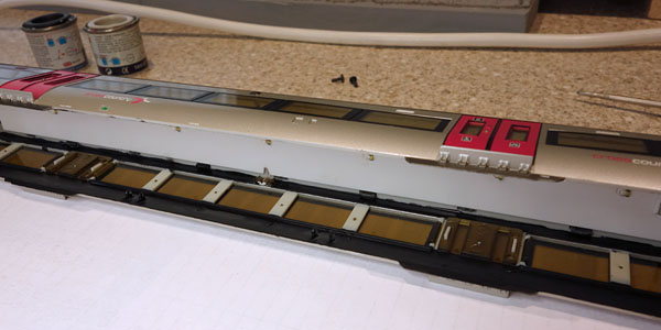
Black paint applied to the inside of the body sides above & below the windows, to reduce light leakage through the plastic.
Black over coated with pale grey below the window level on the end cars. |
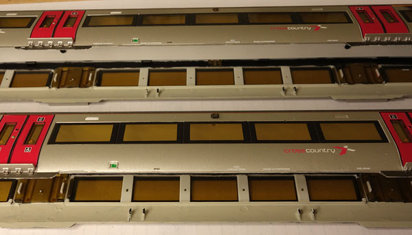
| Adding the current
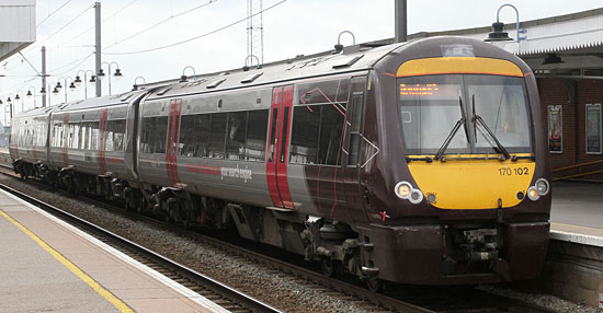
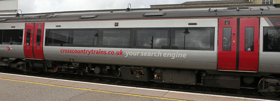
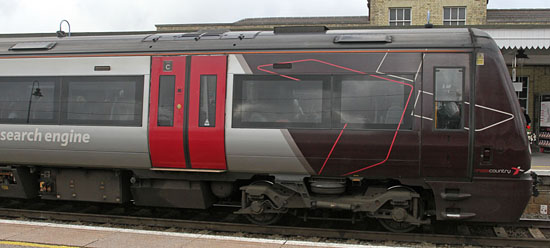
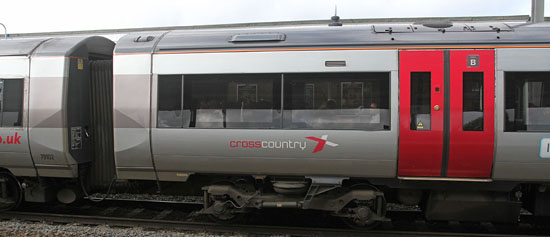
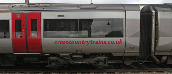
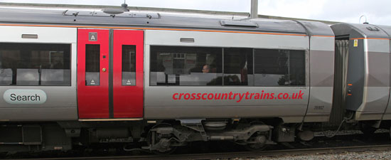
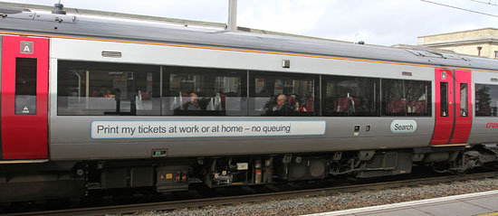
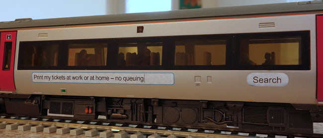
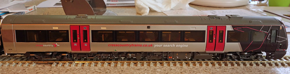
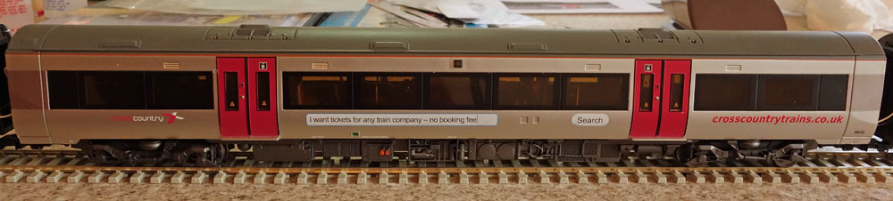
advertising graphics: Our local Cross Country Class 170 Three car units, received some rather less than subtle advertising material a few years ago. I haven't found any off the shelf transfers to replicate this in 4mm. However, John from Precision Labels and Decals advises that because of a huge amount of ongoing work, there is a long queue for custom work... but.... if I can prepare the necessary artworks myself, he can print them for me with a minimal delay. So the opportunity is there! First a sequence of photos at Ely station reveals the scope of the work ahead: By a complete fluke, the train is 170 102 which is the subject of the Bachmann model! Beginning with the lead car:
Judging from other photos, the labelling looks identical from left to right, whichever side the train is viewed from. So eg the A car has "Print my tickets etc" on the right hand side (cab forward) and "Crosscountrytrains.co.uk etc" on the left hand side. (Hope I'm correct as I'm not sure I'd have time to get through the subway at Ely station quickly enough to check out both sides of the same train!)
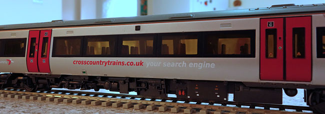
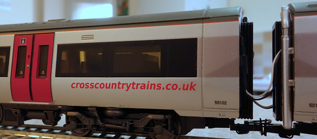
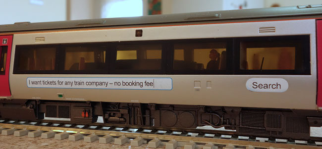
The next stage involves a ruler, the Bachmann's 170 and some careful measurements of full screen versions of the above photos. A font search identified the black text on the white as Arial 7pt. However I was unable to find an exact match for the red and white text font. But.... when reduced in size to the 4mm scale equivalent, most of the finer detail is not so noticeable and in fact Arial Bold Italic looks close enough, at a shade larger than 11 pt. The long white rectangles scale to 67mm long and 4.8mm high, with a narrow pale blue outside edge and rounded corners. The search buttons have semicircular ends 4.8mm in diam, with 9mm straight centres. Next the artwork files required for printing. The decals are printed on to a transparent substrate and the printer must be able to print in white as well as colour. My target printer is the ALPS 5000 type used by Precision Labels & Decals. The recommendation is to generate separate PDF files, to describe the printed area for each colour to be printed. The PDFs, however are to use black for the printed area (not the actual colour, which I guess is selected individually, before printing. The recommended drawing tool is Serif Pageplus, but as I don't have that application, I used Photoshop Elements instead....... bad idea! Having created the necessary PDF pages at 600dpi, I discovered that the file size for each page was over 90MB. Too big to email and I'm advised, too big to process at the other end if sent on a USB stick! This seemed a bit excessive for a single page, but as its a bitmap of a 600dpi A4 page, in fact its what you might expect! So..... plan B: I now have a copy of Serif Pageplus X8 on the way and I've had a play with the free version downloaded from the Serif site. Its certainly easier to create the images than on Photoshop Elements, but unfortunately the freebee wont provide PDF outputs, which is why I need full version V X8. This application uses vector graphics which I understand should result in much smaller PDF files. But..... In fact I don't have to wait till it arrives, as having been in email contact with John asking some probably pretty dumb questions about file formats, he actually generated the Serif outputs himself while explaining what I needed to do....... and over a weekend! ...... I've just received the decals (on the following Tuesday morning!) fantastic service!!!! After making a bit of a mess removing the first of the original Cross Country Logos (that sit where the new decals will go) I've now found a technique that has worked successfully on the second logo. A suitably sharpened wooden cocktail stick seems to scratch away at the logo without penetrating the underlying paint. Fortunately the worst of my first attempt should be hidden by the new decals: ....... and indeed it is! some of the close ups below align well with the real train photos above....
And looking at the entire train:
Now back to that video! |
||||||||||||
Once again, you've read the book, now watch the video! Click here to watch the Class 170 video on Youtube
| Supplier website links:
The photos of real class 170s were taken on the Cambridge-Ely line. The photos of the model were taken hand held on the kitchen worktop. |