A second Voyager DCC conversion and LED Lighting update. This time a Bachmann Class 220 Voyager 4 car DMU is equipped with chip LEDs and hazard lights
|
A second Voyager DCC conversion and LED Lighting update. This time a Bachmann Class 220 Voyager 4 car DMU is equipped with chip LEDs and hazard lights |
|
|
Introduction: This page describes how DCC decoders, correctly operating external LED lighting and hazard lights were incorporated into a second Cross Country Trains variant of the Bachmann Voyager, this time a 4-car Class 220 (OO gauge). Note that the smaller pictures can be enlarged by clicking on the image. |

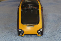
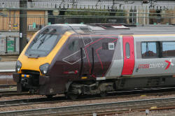
Cross Country Voyager, showing the bright right hand daylight headlight and much dimmer upper and left hand marker lights
| DCC Conversion Approach: The plan is to use an ESU LokPilot V4 decoder in the centre power car and TCS type FL4 decoders in both the leading and trailing cars, providing correct operation of headlights, marker lights and rear lights during day or night running plus hazard lights for station stops. External Lighting Modifications: The Bachmann model includes bulb lighting which illuminates the external light lenses via plastic light pipes. The original lights provide correct daylight operation, but offer no night running option. The bulbs draw enough current to run hot, and have a finite lifetime. They will be replaced by LEDs. Both lower light-pipe assemblies will be removed, and the headlights, lower marker lights and rear lights, will be changed to individual chip LEDs. The top marker light-pipe will be retained, illuminated by a new tower style LED device. The DCC decoder programming will be arranged to handle correct day and night running of the lights via function buttons 0 and 1 respectively. (For day running, right hand headlight, left hand and top marker lights in the forward car plus both rear lights in the rear car. For night running, left hand headlight, right hand and top marker lights in the forward car plus both rear lights in the rear car). The hazard lights in all cars will be switched on via button 2. |
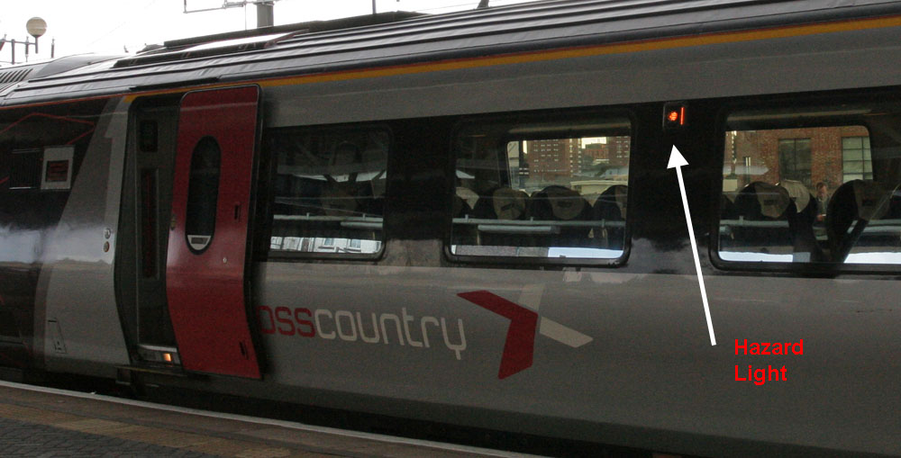
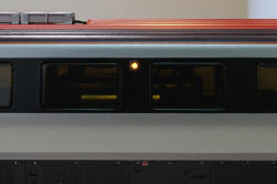
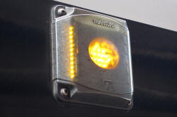
Voyager Hazard Light (click on the image below to see a close-up)
The hazard lights in a passenger car, normally only illuminate when the doors are open.
If they illuminate when the doors are closed, this indicates that a malfunction has occurred
is one of the other car systems connected to the hazard lights, such as the brakes.
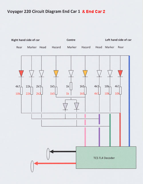
| Circuit Diagram for
end car 1 & 2 lighting: Note: The intensity of the lights utilizing chip LEDs glued to the lens assembly can vary considerably due the loss effects of different glue thickness etc. The values shown below were established for the model concerned by experiment and will almost certainly require adjustment for other similar models. They are included here to give an idea of the likely range of values. (Car 1 in black & car 2 in red)
|
| Achieving Access to the
end cars and removing the original bulb lighting Details of how to dismantle the end cars and remove the original bulb lighting can be found in the previous Voyager update page at http://s374444733.websitehome.co.uk/class-221/index.htm (Then use the back button to return here.) |
| Replacing the missing
lenses: The lighting lenses forming the front ends of the original light pipes are cut off and glued back in place (at the correct angle) using a small amount of clear adhesive to bond them to the upper body shell assembly.
Lower light lenses refitted
|
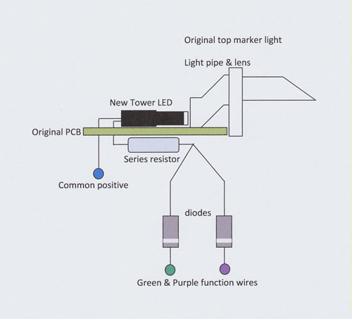
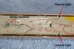
Fitting the new LEDs:
|
| Fitting the FL4 decoder,
programming and testing: The decoder wires are trimmed and connected as shown in the circuit diagram, with the decoder mounted on a double sided foam tape pad immediately behind the PCB in the roof of the car. The decoder wires are glued to the roof, so that they are not obvious when viewed through the windows. The car is programmed and tested by connecting the red and black decoder wires directly to the DCC controller. (See the table below for the programming CV values, in the Leading car FL4 column.)
After a satisfactory test, the decoder red and black leads are disconnected from the DCC controller. The original flying lead connector assembly on the chassis is removed from the small PCB near the front of the chassis unit and the red and black decoder wires are soldered directly to the PCB pads. (The PCB track pads terminate the chassis wheel contact red and black wires.)
|
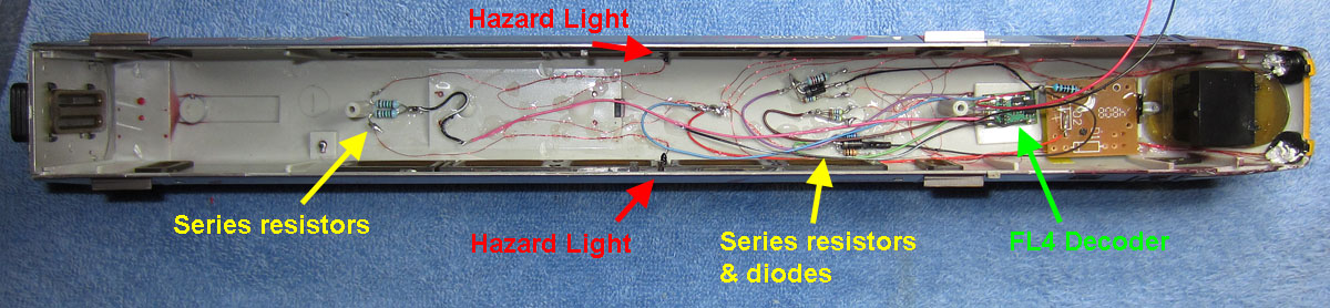
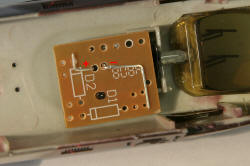
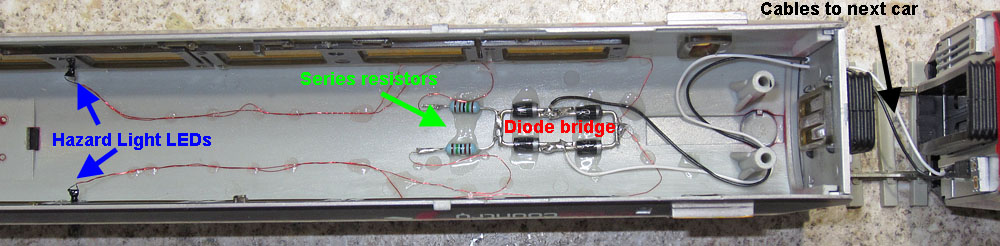
Decoder, LEDs, diodes and series resistors in place
| Programming the end car CVs:
|
||||||||||||||||||||||||||||||||||||||||||||
| Completing the end car
assembly: Now that correct operation is confirmed, the upper body shell is re-fitted to the chassis unit (using the clips and screws). If necessary, any breakages associated with the front lower bodywork are made good (this often becomes detached during the initial separation of chassis and upper body). This completes the end car modifications. |
| Modification of the power
car: The modifications to the power car concern the motor wiring, which must be changed for DCC operation. Also hazard lights are fitted and a miniature connector is added, to power the hazard lights of the unpowered centre car in parallel with those of the power car. The upper body shell is separated from the chassis, by first removing the 4 screws and then easing the upper body sides apart, to release the 4 body side clips. Make a note of the orientation of the upper body shell with respect to the chassis, as it only fixes correctly one way round (due to asymmetric side clips). |

Power car fixing screw locations on similar Class 221
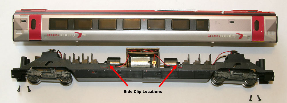
Chassis separated from upper body shell on similar Class 221
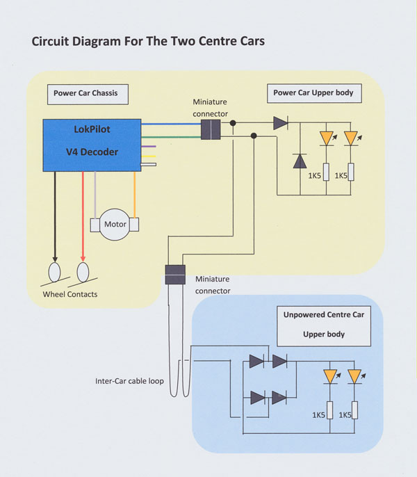
| Circuit Diagram for
the two centre cars: Note: The diodes in the power car prevent damage to the hazard light LEDs if the connector between chassis and upper body is inserted with the wrong polarity. The diodes in the un-powered centre car, enable the hazard lights to operate with the inter-car connector connected either way round.
|
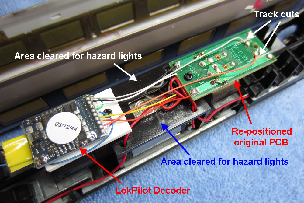
| A problem with the hazard
light LEDs : The clearance between the hazard light LEDs inside the upper body shell, and the original PCB fitted over the motor housing, is not sufficient to prevent a significant risk of damage when the car is re-assembled. To get over this problem, the area above the motor housing near the coach side walls is cleared by re-positioning the component boards above the flywheels. The capacitor on the original PCB is removed (not necessary in a DCC environment). However, the coils in series with each motor terminal are retained. Two track cuts are made on the PCB to separate the supply end of the coils from the wheel contact tracks. The board is then fixed to one of the motor housing screw housings, overhanging the flywheel at the forward end of the car. A 2mm plasticard shelf is screwed in place over the other flywheel and the decoder is fixed to this via an adhesive foam pad.
|
| Connecting to the upper
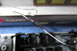
body hazard light circuit: The hazard lights are fitted in the same way as previously described for the end cars but here, a miniature connector is used to couple the chassis based circuitry to the upper body shell.
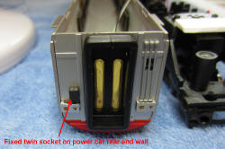
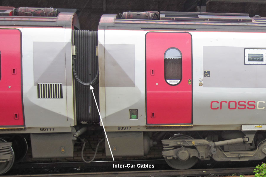
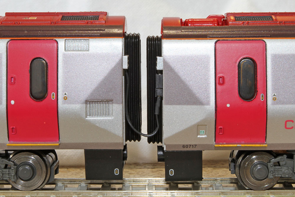
Miniature connector The external connector to the adjacent car: A similar style connector is used to couple power to the adjacent centre car. This time, the socket is fixed to the end wall of the power car. The twin cables from the adjacent car will be plugged into this socket when the cars are coupled together.
Inter-Car cables on a real Voyager |
| Completing the power car
assembly: The upper body and chassis are connected together using the on-board connector pair. With the upper body resting on the chassis, the car is placed on the test track and the ESU LokPilot decoder is programmed as shown in the table below.
Test motor operation and confirm reduced "shunting" speed via button 3........ O.K. Test hazard light operation via button 2........ O.K. If all is well, clip the chassis and the upper body together, then refit the four fixing screws. This completes the power car updates.
|
|||||||||||||||||||||||||||||||||||||||
| Modification of the
un-powered centre car: The car is dismantled and the hazard lights are fitted as before. The circuit shown in the diagram above is implemented with the parts glued to the roof underside. Holes are drilled to allow the flying lead plug cables to be inserted into the end wall of the car.
Car 4 hazard light circuitry glued to the roof underside
The cable is fixed inside the car to prevent its complete withdrawal, but sufficient cable is made available to slide out of the car, to allow appropriate adjustment of the cable loop for unhindered car movement. The car is electrically coupled to the power car and simultaneous operation of the hazard lights via button 2 is checked.......
Hazard Lights check O.K.
The chassis is clipped and screwed to the upper body and this completes the 4 car Class 220 update.
The inter-car cables in place (the mechanical coupling bar is not fitted at this stage) |
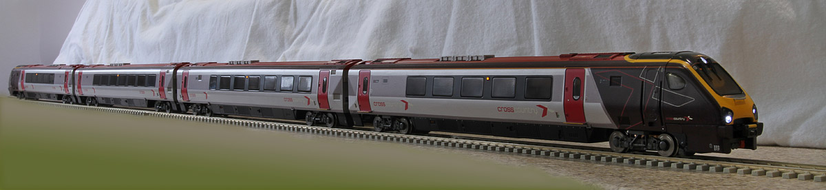
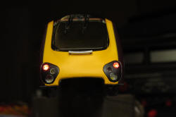
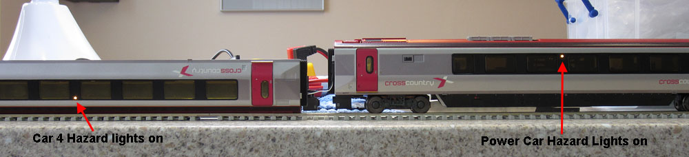
The completed 4 car Class 220 Voyager Train with day running lights and hazard lights on
(Must be a platform on the other side of the train :-)
| Supplier website links:
The photos of real class 220s and 221s were taken at York during 2009 & 2012. The photos of the model were taken on the kitchen worktop using a Canon Ixus. |