Adding Sound, hazard lights and interior coach lighting to the the Bachmann Class 221 Voyager 5 car DMU (already fitted with LED external lighting).
|
Adding Sound, hazard lights and interior coach lighting to the the Bachmann Class 221 Voyager 5 car DMU (already fitted with LED external lighting). |
|
The page starts with the planning & design..............
|
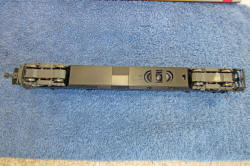
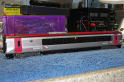
Introduction: This page provides a summary of the process adopted to incorporate a sound system, hazard lights and internal coach lighting to the Cross Country Trains variant of the Bachmann 5-car Class 221 Voyager (OO gauge). (This unit already has its primary external lighting converted to LED technology.) Note that the smaller pictures can be enlarged by clicking on the image. |

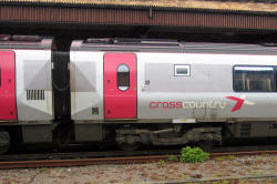
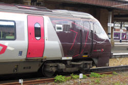
Cross Country Class 221 Voyager at York
| The Sound System: The plan is to fit an ESU LokSound V4 decoder, sourced from DC Kits with "Legomanbiffo" Voyager sound files on board. The decoder will be mounted in the power car, but base reflex speakers will be fitted in the two adjacent cars, with miniature two wire connectors used to link the power car decoder to the adjacent car speakers. The eight ohm speakers will be connected in parallel to present a four ohm load to the decoder. The speakers will be accommodated facing downwards in the space below the coach seating deck. Holes will be cut in the coach undersides below the speaker cones and reflex vents and the coach ballast plates will be cut in two, with both halves refitted beside the speakers. This decoder will also drive the motor residing in the power car. |
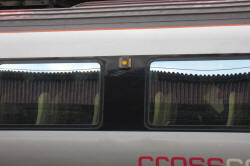
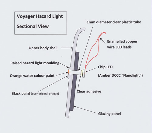
| The Hazard lights: These lights are fitted at the centre of each car on both sides. During normal operation, they illuminate only when the train is at the platform with the doors open.
A 1mm diam hole will be drilled through the centre of each hazard light moulding on each coach side. A 1mm diameter short clear plastic rod will be inserted through the hole. An amber chip LED will be glued to the inside end of the clear plastic tube, providing the light source for the Voyager hazard lights. (See diagram below)
|
| The Internal Coach
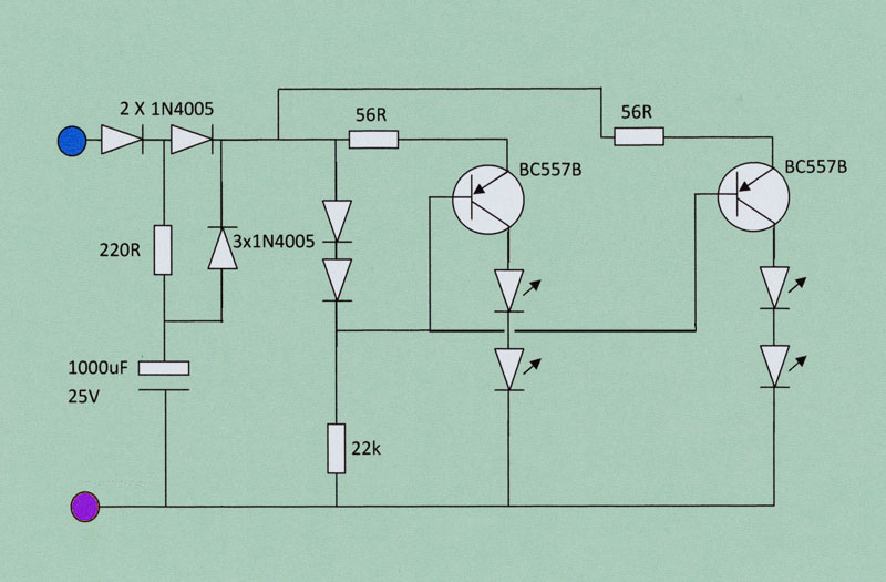
Lighting : Each coach roof will be painted matt white on the inside. Discrete chip LEDs will be fitted to "bounce" white light off the roof in an attempt to obtain a fairly even lighting effect. The LEDs will be connected in pairs to a constant current source, fitted with large anti-flicker capacitors, to keep the lights on in the event of brief gaps in the train power pick-up.
Anti-flicker circuit |
| The Decoder Arrangements: In addition to the LokSound decoder in the power car, ESU LokPilot FX function decoders will be fitted to the end cars and the original TCS FL4 function decoders will be removed from the end cars and refitted to the two inner cars. Five function outputs are needed by the end car decoders but the original FL4s have only four, hence the need to make this change. The track contact feeds from the power car and end cars, will be extended via miniature inter-car connectors, to join together and pass through the two inner cars (where the FL4 decoders will be connected). This arrangement should make the track feeds very reliable and avoids the need to fit additional wheel contacts to the inner cars.
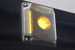
Inter-car cables on the real Voyager |
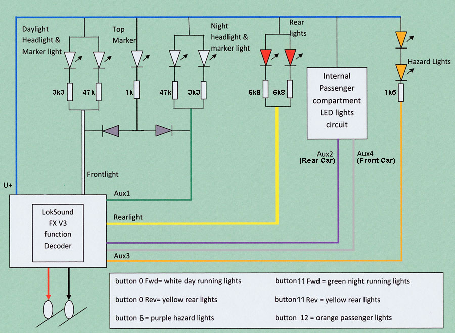
| Circuit Diagrams : The Power Car
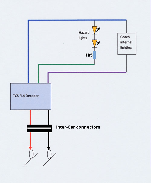
The End Cars
The Inner Cars
|

Decoder Programming:
|
||||||||||||||||||||||||||||||||||||||||||||||||||||||||||||||||||||||||||||||||||||||||||||||||||||||||||||||||||||||||||||
| The LokSound Decoder was
originally pre-programmed as follows:
As shown below, this configuration was later adjusted............. |
That's the plan, now the implementation:
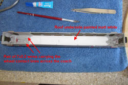
| The sound system: Speaker installation in the central inner car:
Holes were cut in the floor of the central car and front car to permit air movement from the speaker and the reflex vent. The speaker was then superglued to the floor. The steel ballast weight has been sawn in two and both pieces, bolted in place beside the speaker.
Speaker installed in the bottom of the front car |
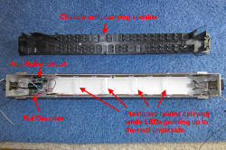
| The hazard lights
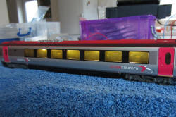
and passenger compartment lighting: New lighting fitted to the central inner car:
A pair of 7-02 white wires are glued to the roof underside to carry the power car wheel pick-up signals through the car. The hazard lights are assembled as shown in the sectional drawing earlier in the page. The roof underside in the central window area is painted matt white. Internal daylight white LED lighting is added, mounted on plasticard cross beams, beaming up and bouncing off the white ceiling. The coach is connected to the DCC controller via the end connectors in the test shots below.
|
New lighting fitted to the front (club-class) Car:

Front Car
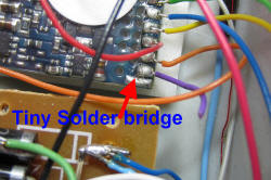
The lighting was checked after programming the decoder CV values and before re-assembly of the car. All worked as expected except for the internal coach lighting, connected to the purple Aux 2 wire. This wire was permanently negative, resulting in the lights switching on as soon as the DCC controller was switched on, with no way to switch the lights off. The spare Aux 4 grey lead was substituted for the purple lead and the CV values amended accordingly. All then worked correctly! Close up photos of the decoder revealed a tiny solder bridge between the purple wire solder pad and an adjacent track. A few careful craft knife cuts cleared the bridge and returned the Aux 2 output to normal operation (in case I have need for a further function output in the future).
ESU LokPilot FX decoder fault identified |
| The Power Car Motor
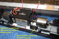
vibration: The motor in the power car is virtually silent when run with the upper body shell removed. However, when fully assembled, the upper body shell seems to act as a sound board, making the motor seem much noisier. The effect can be reduced by "wedging" blu-tack between the lower side walls of the upper body shell and the metal chassis. However I thought it worth trying to reduce the transmission of motor vibration into the chassis, so I've removed the 4 screws holding the motor bracket to the chassis and used double sided adhesive foam pads to fix the motor bracket to the chassis instead, forming (I hope) a quieter resilient mount.
New resilient motor mount Postscript: This really works well....an enormous improvement on the original! |
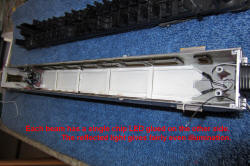
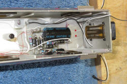
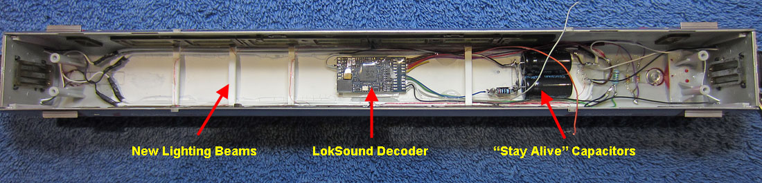
| The Power Car Decoder
location and wiring concept: The hazard lights, internal lighting, adjacent car connectors and through-car track contact wiring all fit in the upper body shell. It makes sense to also mount the decoder (with "stay alive" capacitors) in the roof underside. The top of the motor assembly has to be clear to avoid touching the hazard lights. The chassis assembly wiring has therefore been modified to take the motor wires and the 4 track contact wires to the rear end of the car, where the connections to the upper body shell will be hidden. The decoder will be fitted to the roof underside, directly above the motor, so that it doesn't get in the way of the internal lighting.
Modified chassis wiring
The screw bosses on top of the motor housing have also been removed to leave more room for the decoder in the roof. Two 1000uF 25V "stay alive" capacitors will be glued to the roof underside just forward of the rear bogie pivot tower. |
| The LokSound V4 Decoder
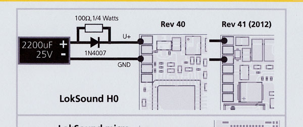
"Stay Alive" capacitor fit: A pair of 1000uF 25V capacitors will be fitted to hold up the motor and the internal lighting briefly if the track feed suffers a "brown out". I'll use a 220 ohm current limiting charge resistor and a 1N4006 diode. The ESU manual shows how the circuit can be added to the decoder.
Diagram from the ESU manual
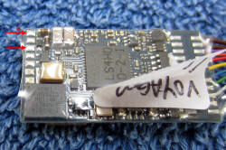
It would appear that my decoder is a 2012 Rev 41 variant as can be seen in the photo below. (click the image to enlarge).
Showing the pads on the decoder |
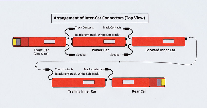
| The Inter-Car Connector
Arrangements: Thought it wise at this point to create a diagram of the the connector arrangements as a mistake here will probably destroy the LokSound decoder and/or the speakers! and that would be very expensive........
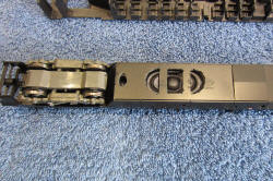
Connector sockets on the rear of the Power Car
Inside the Power Car Upper body shell. (The internal connectors to the chassis wiring have yet to be fitted). |
| Testing the completed
train: All 5 cars have now been updated. First the good news: Connecting up the inter-car plugs and sockets, the lighting all works according to plan. The sound system also operates well and the resilient mount for the motor dramatically reduces unwanted motor noise. Three problems remain: 1) The top speed of the power car is lower than before and this needs improvement. 2) The mapping of the sounds could usefully be improved to get the station stop and restart sounds into a sequential order without needing to re-page. Also, the volume of the motor sounds needs to be slightly reduced compared with the other sounds. 3) The hazard lights are not at a consistent intensity............This one is simply due to me forgetting to paint some of the lights with orange water colour paint (which brings down the intensity to the right sort of level). Addressing the issues: Slow top speed: Possible causes include 1) The long thin cables from track pick-up to decoder and from decoder to motor may have enough resistance to reduce the motor voltage at high speed. 2) The flywheels may be rubbing against the top surface of the adhesive foam pad supporting the motor bracket. 3) The decoder settings may need a tweak. Detailed investigation eliminated the first two possibilities, so I tried adjustment of CV2 (lowest speed step), CV5 (max speed step) and CV6 (mid speed step) and CV53 (speed range within back emf system). I found a compromise that seemed to work OK, but then discovered that the latest English edition 3 ESU LokSound V4 decoder manual has errors in the quoted CV5 and CV6 permissible value range. The manual quotes 0-64. The real range is 0-255 (As in the previous English manuals and also the current edition 3 German manual). With the freedom to enter bigger numbers here. I ended up with CV2=3, CV5=250, CV6=90 and CV53 returns to a default 140. The CV3 and 4 acceleration and deceleration values were higher than I normally use, but after experimenting with smaller values, to confirm the speed range was OK, I reverted to CV3=CV4=60 which I think is somewhere near the original values, and gives a very realistic looking running performance.
Sound adjustments: The volume adjustments available with each sound slot were used to identify which sounds had been allocated to each sound slot. The volume levels were then adjusted to obtain the relative levels that I thought appropriate: (Not necessarily corresponding to the real relative levels).
Revised sound and function mapping aspirations: After running the train on the test track, I can see several opportunities to improve the button assignments and add some additional functionality. I want to arrange the most commonly used sounds within the 1 to 9 range to avoid having to switch to the next function number range. Also I need to separate the hazard light switching from the door sounds button as the lights should go on and off at actual door opening and closing (not right at the start of each sound buzzer sequence). The LokSound V4 has a function output delay feature, that would handle this problem for the power car, but of course not for the other 4 cars! Finally, I want to add shunting mode within 1-9. for slow train movements. The less used sounds and functions are relegated to the second function button range (10-19). The night running lights are also moved from F6 to F11... This will require changes to the end car decoder programming too. The hazard lights are also moved from F4 to F5... This will require changes to the end and inner car decoder programming too. Without an ESU LokProgrammer, this might be a bit ambitious, but I'll plan the changes and we'll see........ (The green areas are unchanged. The yellow areas are the updates.)
I now have a Lenz starter set 100 up and running, which finally gives me the ability to read the loco CVs before I attempt to change any values (not possible with my old Dynamis). I can see how the Aux 1 function is controlled via button 4 (which I will need to move) but I've yet to figure out how Legomanbiffo manages to get the dual button action for his door sounds.....and then only when button 1 has also been activated. Hopefully I don't need to know this, fingers crossed that I don't mess this up when I extract the Aux1 function output though! |
||||||||||||||||||||||||||||||||||||||||||||||||||||||||||||||||||||||||||||||||||||||||||||||||||||||||||||||||||||||||||||||||||||||||||||||||||||||||||||||||||||||||||||||||||||
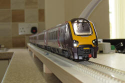 Lead car view on the test track |
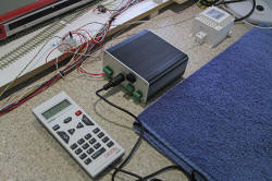 New Lenz controller in action |
| The changes are
done in small bites to make it easy to revert to the original values
if I make an error....... (updating the
yellow sections of the table above as I go) First change ....... Add sound slot 5 to currently unoccupied Mapping Line 19 F13...... Change CV32 to 3, check CVD=CV292 is 64 YES..... Change CVO, CV302 from 0 to 16 Success! 2nd change ........Remove sound slot 5 & add Aux1 Mapping line 11 F5....... Change CV32 to 2, change CVO CV430 from 16 to 0...... Change CVK CV426 from 0 to 4 Success! 3rd change .........Remove Aux1 from button 4: Mapping line 10: check CV32=2, change CVK CV410 from 4 to 0.....Change CVL CV411 from 64 to 0 Success! 4th change ..... Add driver door slam to button 15 Mapping line 21 CV32=3 change CVE =CV325 0 to 4 CVO=CV334 0 to 32 Success! 5th change...... change driver door slam to guards whistle on button 6, mapping line 12 CV32=2, Change CVO CV446 32 to 0 change CVP CV447 0 to 2 Success! 6th change....... Add toilet pressurisation to button 16 mapping line 22 CV32=3 CVE=CV341 to 16 CVO=CV350 0 to 64 Success! 7th change....... Change toilet pressurisation to right away buzzer button 7, mapping line 13 CV32=2 CVO=CV462 64 to 0 CVP=CV463 0 to 4 Success! 8th change...... Change guards whistle to compressor speed-up button 10, mapping line 16 CV32=2 CVP=CV511 2 to 0 CVO=CV510 0 to 128 Success! 9th change...... Change compressor speed-up to flange squeal button 8, mapping line 14 CV32=2 CVO=CV478 128 to 0 CVP=CV479 0 to 1 Success! 10th change..... Change flange squeal to shunting mode button 9, mapping line 15 CV32=2 CVP=CV495 1 to 0 CVM=CV492 0 to 2 Success! 11th change..... Remove right away buzzer from button 11 mapping line 17 CV32=3 CVP=CV271 4 to 0 Success! 12th change..... Add no accel/decel function to button 14 mapping line 20 CV32=3 CVM=CV316 0 to 1 Check CVE=CV309 is 1 Success!
All changes made successfully. ....... Now bringing the other decoders into line with the revised power car settings: |

Every kitchen should have one!
| Changes to the end car
decoders: Move hazard lights to button 5 both cars: Remove from button 4....... Set CV165 & CV168 from 16 to zero. Add to button 5....... Set CV171 & CV174 from 0 to 16. Move night running lights to button 11 Lead car: Remove from button 6....... Set CV177 & CV180 to zero. Add to button 11....... Set CV207 to 4 & CV210 to 2. Move night running lights to button 11 Rear car: Remove from button 6....... Set CV177 & CV180 to zero. Add to button 11....... Set CV207 to 2 & CV210 to 4. These changes have now also been made to the programming tables and button data in the design area of the webpage above. |
| Changes to the inner car
decoders: Hazard light green wire button mapping: Change CV35 from 32 to 64. (The CV Table above in the design area, also modified with this change.) |

On the test track with day running lights and hazard lights on
| Testing the entire train: The revised control arrangements all work really well...............that 'll do nicely! ..........Project complete! |

Night running lights and interior lights on
| Further Adjustments, made
during computer controlled tests: 1. Sound enhancements: The Voyagers I have studied at York Station, exhibit a substantial increase in sound volume immediately before they pull away from the platform. This volume level is maintained as the train leaves the station. Unlike the lower power DMUs (such as 158s) there is only a minimal increase in revs associated with the increase in sound volume. The Legomanbiffo sound files do not exhibit enough increase in sound level. However, the LokSound V4 decoders have a programmable sound fader function. This can be arranged to operate as a sound booster by reversing the button action and selecting appropriate sound levels. To assign the volume booster facility to controller button 19: ...... Set CV 32 to 3 and then CV390 to 8, also CV397 to 8. Reset the master volume CV63 to 80 and CV133 (volume change level with respect to 128) to 75. The procedure is to activate button 19 two seconds before the train actually starts to move. The Legomanbiffo LokSound start delay is a rather long 10 seconds, so button 19 needs to switch on about 8 seconds after initiating the train movement. The volume level is left high until the train stops. Button 19 is de-activated during the wheel brake sound, leaving the train idling at low volume when stopped. 2. Speed characteristics adjustments: For computer control, CV3 was increased to 90 to prevent abrupt starts and CV4 reduced to 24, to allow the PC to bring the train to a halt more quickly. CV5 and 6 were also adjusted to slightly reduce top speed while increasing the speed step resolution at low speed. |
To see a short video of the Voyager on the test track: Click here
| Still Further Adjustments,
as a result of input from Brazil! ...... With thanks to Marcelo! 1. Activating notching: Marcelo has used the notch-up command at departure to successfully improve the engine sound. To do this requires some new button assignments:
The revs & sound level notches up to max over several seconds. This would simulate a max acceleration take off quite well..... However, control is not passed back to the sound system until the loco comes to a halt again! So the rev setting has to be controlled manually for the duration of the journey......holding the "notch-up" key or the "notch-down" key on for approx 1 second results in a single notch change, so this could be considered. |
Summarising the control settings:
| Button | Action |
| 0 | Day running lights |
| 1 | Engine on/off |
| 2 | Hi Horn |
| 3 | Lo Horn |
| 4 | Door open / close |
| 5 | Door hazard lights |
| 6 | Dispatcher whistle |
| 7 | Right away tones |
| 8 | Wheel flange squeal |
| 9 | Shunt mode |
| 10 | Compressor speed-up |
| 11 | Night running lights |
| 12 | Internal lighting |
| 13 | High pressure windscreen washer |
| 14 | Zero momentum |
| 15 | Drivers door slam |
| 16 | Toilets pressurisation |
| 17 | Notch-up |
| 18 | Notch-down |
| 19 | Volume boost |
| Supplier website links (to
be updated with new suppliers):
The photos of real class 221s were taken at York during 2012. The photos of the model were taken on the kitchen worktop using the same Canon Ixus 220HS camera, except for the last two which came from my SLR (to get a greater depth of field). |