Early Brush Type 2 Diesel Locomotive:
| Sourcing our
model: Brush Type 2 diesels entered service in the Eastern Region of British Railways during the late 50s. These locomotives frequently pulled coal trains through our village station in the days before the clean air act drastically reduced coal consumption in the London area. Hornby have not produced the initial Mirrlees powered variant of this locomotive for quite a number of years. Although its still possible to buy these in "new" condition, this is a risky undertaking as many of the original models incorporated chassis blocks contaminated with lead.... this resulted in the blocks swelling in an unpredictable way, up to several years after manufacture, causing severe damage to the body shells. Currently Hornby produce a very basic Railroad model of the early Brush Type 2, based on dated moulding tools inherited from Airfix. This was not regarded as an acceptable model for our village layout use. Quite recently, good quality Class 31 locomotives from a much later time period have been released, but these have many detailed differences to the early Type 2s. However, saving the day, Kernow Models have recently contracted Hornby to produce a limited batch of 350 good quality models of the correct Type 2 variant. Unfortunately, the livery chosen is a one-off experimental brown/ochre colour scheme exploring higher visibility solutions. But a decision was taken to obtain one of these locomotives and repaint it in BR green, as the best route towards a good quality late 50s Brush Type 2, with a stable chassis block. |
Brown/ochre liveried Brush Type 2 as delivered from Kernow Models.
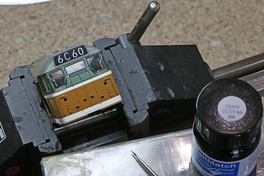
| The Green
Transition: Railmatch BR Green was chosen to paint over the top of the original orange/brown coloured parts of the locomotive. It proved unrealistic to remove the windows as they were very securely bonded in place, so the first task involved very carefully hand painting the window frames green, using a very fine brush.
Using very fine abrasive paper, the raised numbers and BR logos were sanded flush. The model was then masked to cover up the windows, roof and all below the top of the upper white line. Several light coats of Railmatch BR green spray paint were then applied between the roof and upper white line. When dry, the process was repeated to spray paint the area between the two white lines. Finally the area below the bottom white line received the same treatment.
The imperfections were then made good using white or green brush paint. Railtec Transfers have a complete 4mm early Brush type 2 transfer sheet that they can customise for specific numbers. D5572 has been chosen as a March based locomotive that very probably saw service through our village station. The transfers have now arrived, so next steps (after wiring up the body) are to gloss over the local area of each transfer using enamel gloss varnish. The transfers will then be applied and when they are completely dry, the whole body will be sprayed with matt varnish (except the window areas which will be masked). Finally, the cab door handrails will be glued back in place. |
| Selecting the
sound decoder: During the late 50s and first half of the 60s, A Mirrlees Diesel engine powered the Brush Type 2 locomotives. Unfortunately these engines had a disastrous record of reliability and after a successful trial, BR decided to re-equip the entire fleet of circa 200 locomotives with the English Electric engine used in the Class 37, down-rated in line with the capabilities of the Brush Type 2 generator and traction motors. The engine change was carried out in the mid 1960s. The locomotives (originally TOPS code Class 30) were reclassified as Class 31 when commissioned with the new engine. The sound recordings available for incorporation into DCC sound decoders have all been made using the remaining preserved Class 31 locomotives as no Mirrlees examples survived into the digital age. There have been attempts at simulating the original Mirrlees diesel engine sounds, but the accuracy of the results is somewhat doubtful. The Mirrlees engines used in Class 37/9 and Class 60 locomotives (6 & 8 cylinders respectively) are very different from the 12 cylinder type used in the type 2 and as a result, sound recordings from these locos are not useful for type 2 simulations. So it has been decided to use a Class 31 Legomanbiffo LokSound V4. This will later be compared with the Paul Chetter Zimo MX645 solution in my Network Rail Class 31. (If the Zimo solution is deemed more like the Mirrlees, then a swop will be considered.) A downward facing bass reflex speaker with 20x40mm drive unit will be used, located in place of the Hornby model fan assembly.
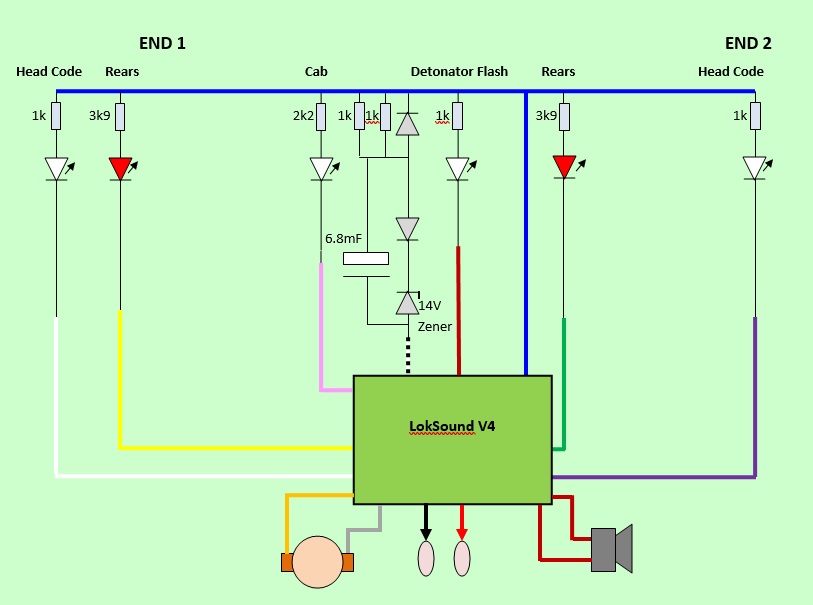
Bif's published Function Map:
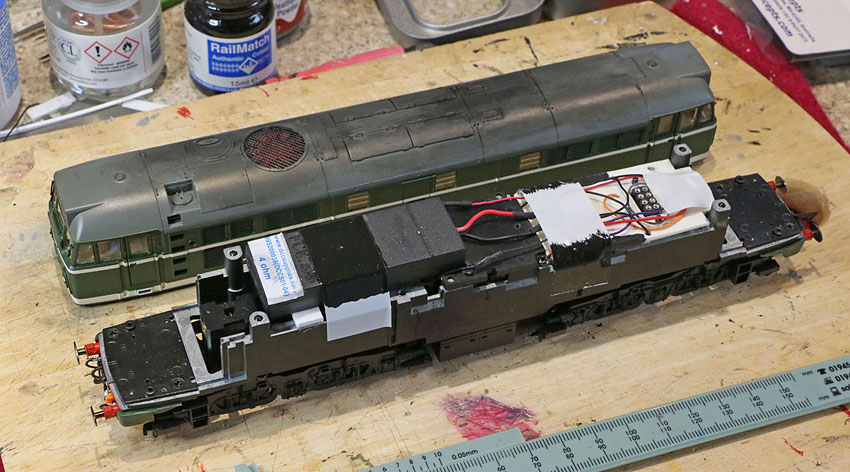
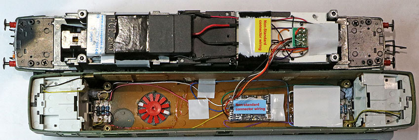
The original fan mechanism has been removed from the chassis to make room for the speaker. The red fan has been weathered and glued directly to the undersideof the roof vent, using two small plasticard spacers. Diesel soot stains have been added on the roof. A 4 ohm bass reflex speaker is now mounted on the chassis. The original Hornby PCB has also been removed and replaced by a simple plasticard substrate supporting an NMRA 8 way socket with no function wire connections but including two non-NMRA standard speaker connections in their place. |
| Fitting the
electrics: The new sound decoder (and some new LED series resistors) completely replace Hornby's main PCB assembly, which is consequently removed. Previous experiments suggest that a 4 ohm DCC Supplies bass reflex speaker using a 20x40mm drive unit works well when fitted in place of the Hornby fan assembly, facing downwards. A super capacitor is used to provide a limited degree of protection against track contamination. This is a 15 volt device so over-voltage protection is provided by a simple zener diode circuit. The decoder is mounted in the body shell roof, with electrical connections to the chassis assembly, made via the modified 8 pin DCC connector, which has been customised to exclude the function control wires, but to include (non-standard) speaker wires. A warning label will be added to indicate the non-standard nature of the revised connector (in case I forget :-). A white chip LED is now glued to the roof underside directly over the driver's cab. Circuit Diagram: Experiments with a bench power supply provided a subjective view on the optimum series resistors to be used when powering up the LED lighting. The values are 3k9 for the rear lights, 1k for the head code boxes and 2k2 for the cab light.
Circuit Configuration (Aux3 and Aux 4 outputs are normal function outputs on Bifs V4 variation, so buffers are not required.)
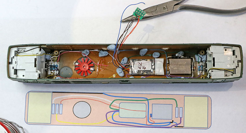
Inside the body shell. Wiring up the decoder and stay alive supercap. is under way. The blue tack blobs are being used to hold the wiring in place while the retaining glue dries.
Wiring now complete including reminders (mainly for my benefit) that the 8pin sockets are now not wired to NMRA rules. |
|
Transfers and cosmetics:
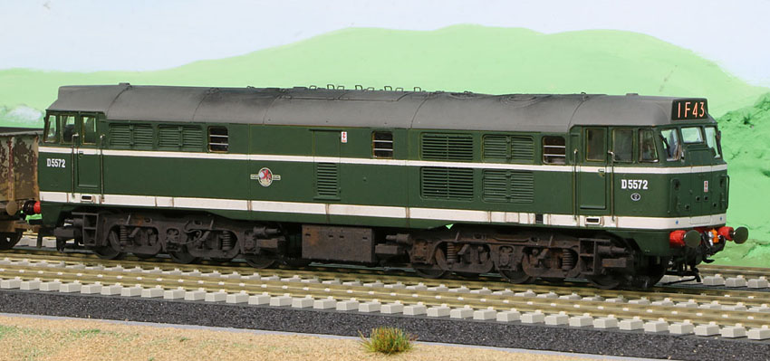
New transfers for D5572 are now in place and the cab door hand rails have been put back in place. The Railtec Transfer sheet included customised numbers and all other essentials. The individual transfer application went very well, with no hint of silvering.
The bogies have been weathered and a there are signs of minor corrosion appearing on the lower body sides.
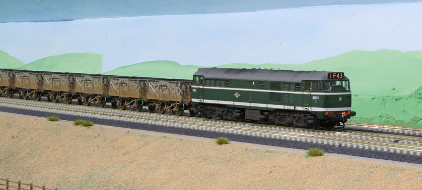
The Type 2 hauls a Yorkshire coal train, heading towards London. |