Network Rail Class 31 and an Ultrasonic Test Train...
Hornby's Class 31
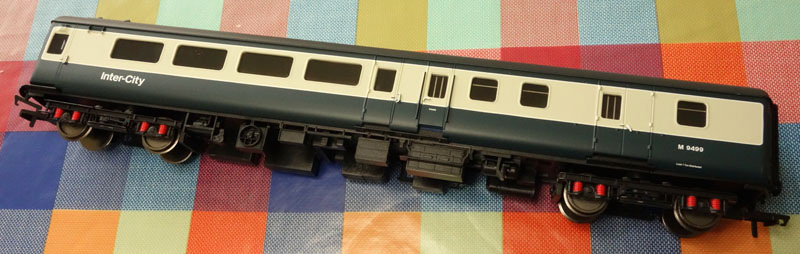
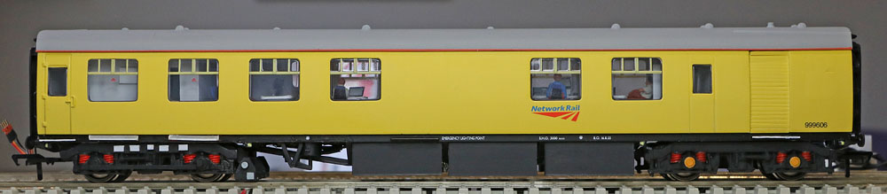
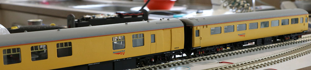
| Introduction: Hornby's Network Rail liveried Class 31 has just been re-released. These now vintage locomotives can still be seen in service, providing motive power for Network Rail Test Trains throughout mainland UK. One of the most common trains are the Ultrasonic Measurement Units (or UTU). This project attempts to replicate a Class 31 powered UTU train in 1/76 scale. The Class 31 locos are often fitted with a bank of 5 Infra-red spotlights at the forward end (in addition to normal running lights). The train consist will be made up of a Mark 2E Brake Runner with all windows blanked off, immediately behind the loco. Next is a standard second open Mk2E brake runner/crew coach. Followed by the measurement car (999606), which is a highly modified Mk1 second open equipped with the measurement system & its external lighting. Finally at the rear of the train is a DBSO in the form of a Mk2E brake coach, converted to include a driving cab at the rear end. These can also have an array of 6 infra-red spotlights fitted plus normal rear facing running lights. The project involves: Adding DCC controlled lights and a sound system to the locomotive. Modifying a Bachmann Mk1 and three Hornby Mk2E coaches to the new configurations. Painting the coaches in Network Rail Yellow, with appropriate NR logos. Adding DCC controlled lighting to the DBSO & coaches. |

The Hornby Class 31 Locomotive:
| First the bad
news:
Some initial Hornby
quality
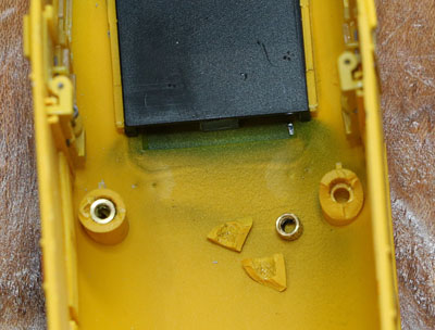
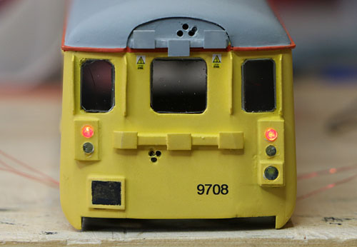
Issues: First the minor fixable issues: Straight out of the packing, one of the jumper lead cables was bent out of shape and one of the headlamps had an off centre lens and a small piece of plastic flash over the aperture. (See pic. below)
(Not shown: The headlight lens is offset to one side behind the aperture.)
More annoying: One of the fixing screw bushes had broken away from its mounting pillar inside the body. In fact the remaining 3 screws hold the unit together without any obvious difficulty, so not a problem.
Normal Design related issues: The headlamps are very dim compared to the marker lights and the lens is well behind the headlight aperture front. (All fixable.)
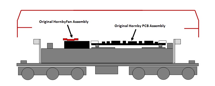
Intriguing fan puzzle: A red multi blade fan is fitted below the roof grill, but although a mounting framework is in place, above a flywheel with a drive band groove provided, there is no mechanism fitted to drive the fan from the running gear in the normal Hornby fashion. Is this deliberate or an assembly omission? Not a problem for me as the fan assembly has to go, to make room for a 40x20mm speaker, venting through the roof grill!
Then the good news: A quick DC analogue test revealed smooth and quiet running. Apart from the issues mentioned above, this looks an impressive model and to my inexpert eyes, it looks a good representation of Network Rail's elderly motive power. Can't wait to get started on some updates! Although the lighting assemblies use a common negative supply, I'll be replacing the headlight LED (& lightpipe) so I'll be able to hook up the separate marker and rear light assemblies without needing to use inverter transistors.
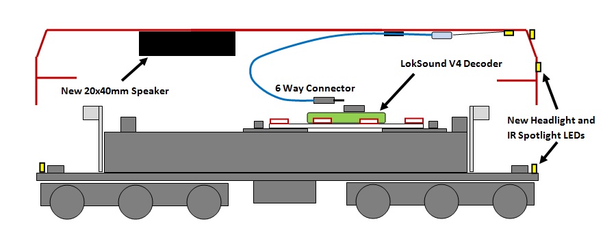
Speaker Arrangements: ESU 50334 20x40mm speaker in standard ESU enclosure, located in place of the Hornby fan assembly. Speaker plus enclosure glued to the roof underside, with the speaker venting upwards through the roof fan vent. Speaker assembly sealed around the front edge to the roof, using Blu Tack to seal the ends.
Decoder Function Mapping: Taking Bif's original mapping and adding lighting compatible with the DBSO decoder, which will have the same address:
Programming for the Lights:
|
Electrical Hardware Approach:
| 1) Electrics: I've decided to go with Legomanbiffo's Class 31 LokSound V4 decoder in the locomotive and a supporting ESU LokPilot FX V4 function decoder in the DBSO. Miniature electrical connections will be fitted between the DBSO and the Measurement Car and the Crew Car, to place the coach lighting under DCC control via the LokPilot FX in the DBSO.
|
|
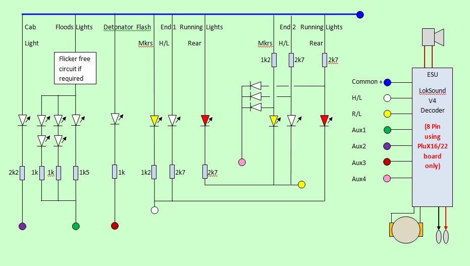
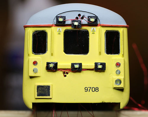
The Class 31 Locomotive: Now that the Hornby model has arrived and I've had a close-up look.... I've decided to replace the original dim headlights with new separate LED devices, so, as the markers are separately wired, I can forget about negative ground lighting boards and use a slightly simpler circuit:
Revised Circuit....... or so I initially thought!!!!
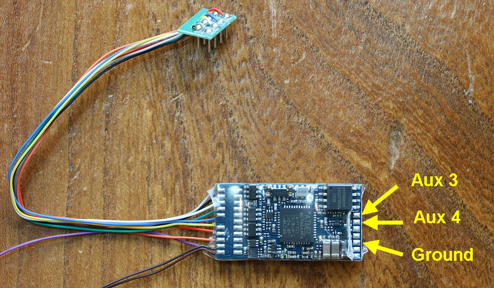
Bif's LokSound V4 decoder has arrived.... the non-cabled connections are shown above. Curiously, the 8pin LokSound V4 appears to be a cabled version of the PluX16/22 connector variant judging from the track pattern. This turned out to be far more important than I initially realised..... after trying to debug a failure on the part of the decoder to correctly drive the two MOSFETs providing Aux3 and Aux4 function outputs, I came across section 6.10.4.2 in the manual, which indicates that PluX16/22 variants of the decoder incorporate amplifiers in the Aux 3 and Aux 4 outputs, so no external MOSFET buffers are in fact necessary with this hardware variant of the decoder! (Just connect the load between common positive and the Aux3 or Aux4 solder pads.)
Showing the redundant MOSFETs hooked up to the ground, Aux3 & Aux4 pads. While these would be required on virtually any other LokSound V4 variant, it seems that the inverting buffer amps are already in place in the PluX16/22 version which ESU must have fitted with an 8 pin plug and provided to Bif and Charlie!
Circuit Diagram for PluX16/22 version only of the LokSound V4 as used by ESU in the 8 pin unit provided by Bif & Charlie.
Original Hornby Configuration.
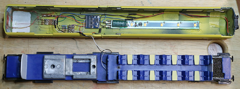
Decoder Installation: The Hornby fan assembly was removed to provide room for the speaker. The Hornby main PCB was also removed completely. A slightly smaller plasticard substrate was then glued in its place to sit between the original PCB support columns. Maplin copper strip board was fitted to the substrate ends to provide anchor points for the locomotive wiring and the LED series resistors. The LokSoundV4 decoder was glued to the centre of the substrate, with the Aux3 & 4 solder pads facing upwards. A TCS 6 way miniature connector was used to couple the upper body shell circuitry to the chassis mounted substrate & decoder assembly. Upper body shell components: The speaker was fitted and sealed into into its enclosure. the enclosure was then glued to the roof underside, directly below the circular roof fan aperture. The cab light and infra red spotlight LED wiring was connected via series resistors glued to the inner roof, to the 6 way connector. The loudspeaker wires were also routed to join the 6 way connector. The connector wires were arranged to lay flat between the decoder and the roof when the loco was re-assembled.
Modified to accommodate the new speaker, sound decoder, new LEDs and 6 way interconnect. |
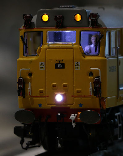
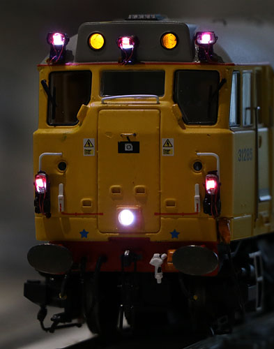
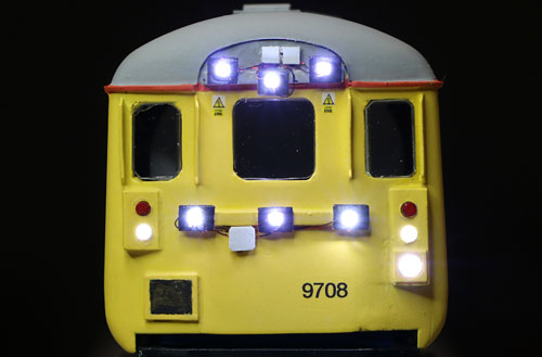
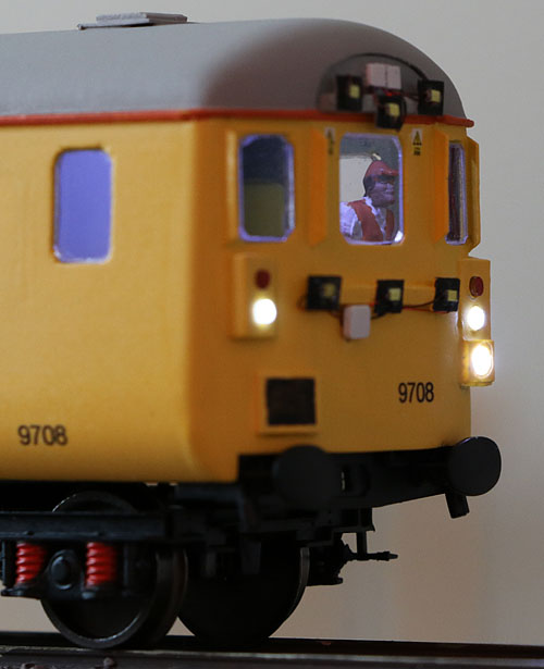
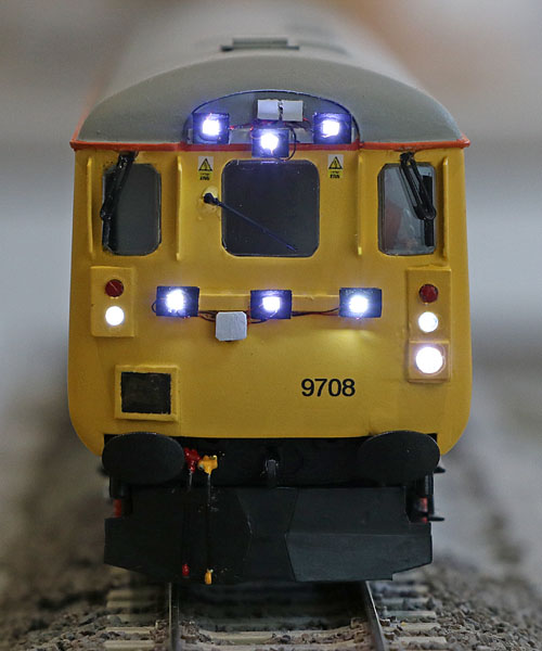
| Testing the
lights:
The lights at the rear (train) end of the loco can be disabled when a train is on the hook. |
| Running the Class
31 under DCC control: The loco ran fairly well with the original Bif decoder CV settings, but I've made a number of changes which I think improve operation a little: CV 2 was changed from 1 to 2 to bring the first speed step into line with subsequent steps and CV6 was reduced from 80 to 60 to slightly expand the slow speed region of the control characteristic. The loop control CVs had some curious values. I was sufficiently concerned about these, to make some adjustments: The Hornby model has two large flywheels and a good sized motor. With this arrangement, I would expect the value of CV55 (which relates to the momentum of the motor) to be in the region of 100. However the "as received" value was 18, which seems far too low. In my experience, an optimum motor and flywheel arrangement like the Class 31 works best with the loop control CVs close to ESU's default values, so I shifted CV52 from 18 to 30; CV54 from 93 to 50 and as already mentioned, CV55 from 18 to 100. The locomotive and its sound system run very well. |
|
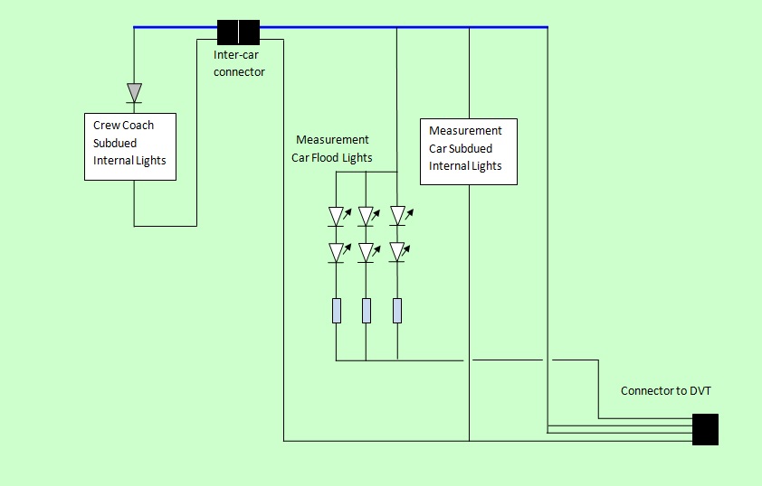
The Test Train coaches The electrical circuitry: ................
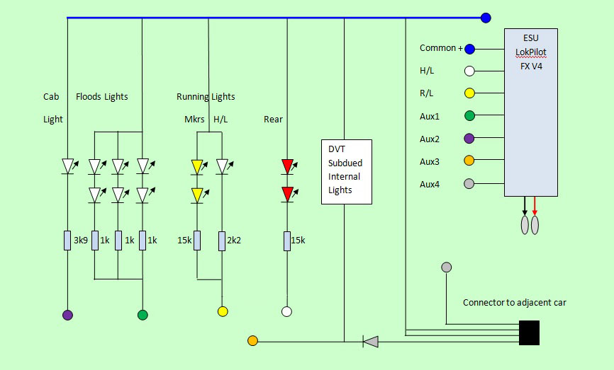
DBSO Circuit Diagram (detonator flash LED now removed). I may need to add flicker protection to the flood lights later, but on the test track they are showing no sign of discontinuities so far.
Measurement Car and Crew Car Circuit Concept. (See later on for the final more complex circuit.)
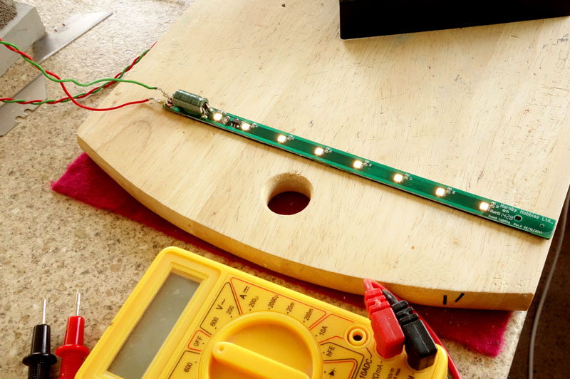
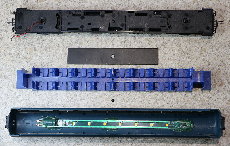
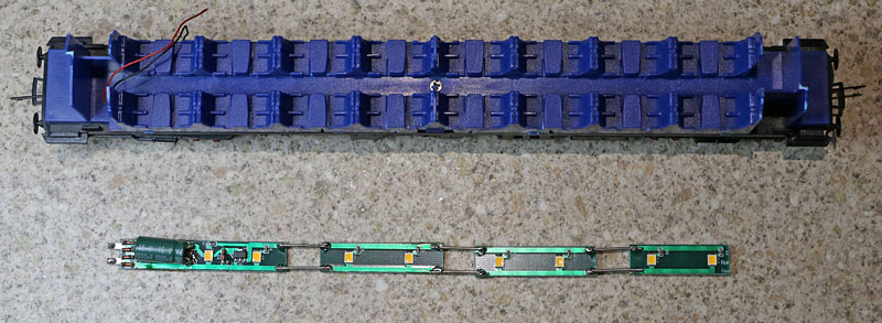
Coach Lighting with anti-flicker protection: Initial evaluation of Hornby's Mk2E lighting circuit reveals a very effective circuit with excellent flicker protection and good distribution of the warm white lighting LEDs.
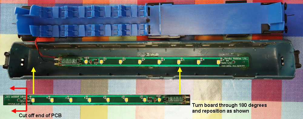
The only thing that lets the system down is the length of the PCB (about 5cms too short for a Mk2 coach) and the location used in the coach roofs to position the assembly. These combine to give dark areas at one or both ends of the coach. I will divide up the Hornby PCB to increase the span covered by the 8 LEDs in the crew coach. In the DBSO, I'll simply chop the unused end of the pcb off and reverse the board in the DBSO roof, to place the capacitor end within the original guards area, re-locating the board to properly illuminate the passenger area at the non-driving end. (A new cab light will be provided for driving area illumination.)
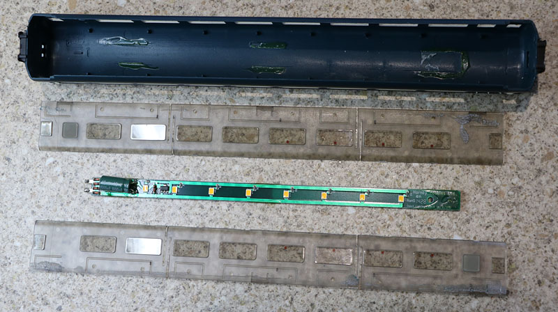
Showing how the DBSO lighting board can be used more effectively. (In the end, I also removed three LEDs to keep overall illumination levels in line with the crew coach.)
|
|
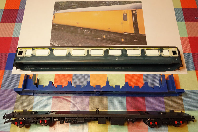
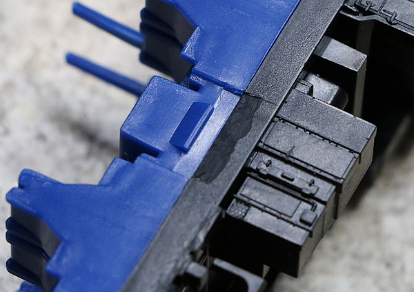
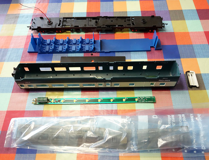
Modifying Hornby Mark 2E Mechanical Coaches:
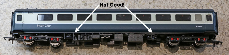
Hornby's Mk2E coaches have an obvious appearance problem, due to the mm or so of black underframe, visible below the coach side panels. The side panels should extend lower to completely hide the side of the underframe. A simple fix is possible to drop the body just enough to eliminate this problem......It may result in inaccuracies elsewhere, but the solution is good enough for me! In order to modify and finally spray paint the coach sides with Network yellow paint, the windows ideally need to be removed. After recently failing to find a way to remove Hornby Mk3 coach windows intact, because of some very effective bonding by the Chinese manufacturers, I was delighted to find that the Mk2 glazing can be carefully removed with hardly any dramas! Its only bonded near the bottom of the coach sides and the glue bond can be broken with relatively little force.
Easing the glazing away from the coach side. |
Coach Conversion Work:
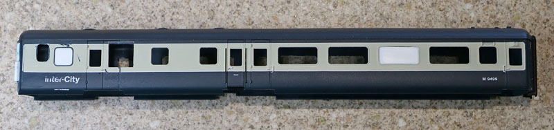
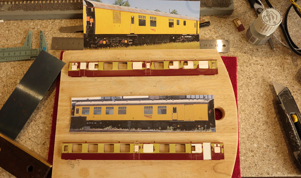
| 1. The Fully
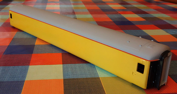
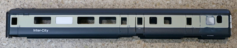
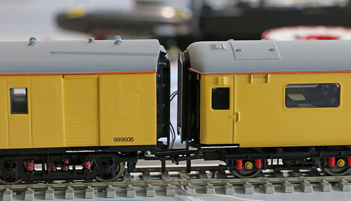
Plated over Mk2E Brake Runner Coach The (unlit) Hornby model was dismantled by unclipping the upper body shell from the chassis. The seat moulding was unscrewed and removed. The glazing pieces were carefully broken out (intact). The frames of all the large windows were trimmed flush & 1mm thick plasticard filling pieces cut and glued to fill the window apertures. The few gaps were filled and the plasticard sanded flush, ready for spraying.
The loose weight was super-glued to the chassis top and minor trimming was carried out to enable the upper body to sit approx 1mm lower on the chassis, just covering the chassis upper side pieces. (The seat moulding will not be refitted.)
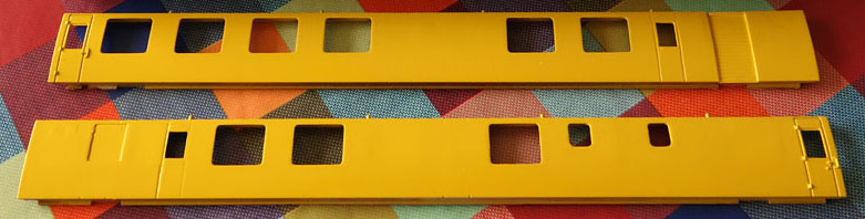
My sophisticated spray booth in the loft! :-) Primed, patched, sanded, re-primed......then the yellow goes on.
Ready for the transfers.
Transfers on, matt varnish on, windows in....... Clips modified & chassis back on.
|
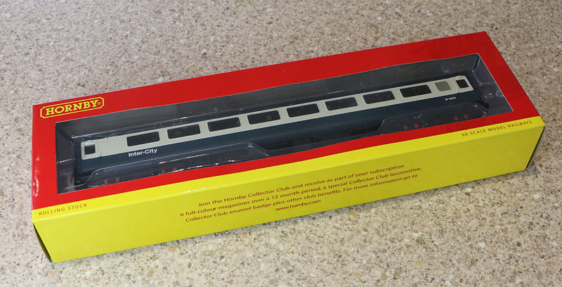
| 2. The Crew Coach
(or is this another brake runner?) A second open Mk2E coach, with lighting fitted is the starting point..... Just need to dismantle and remove the glazing ready for spray painting. Then make the necessary mods to lower the upper body shell on the chassis. Add a bit of detailed painting to the seating & tables & a couple of crew. Plus expanding the internal lighting coverage by splitting the PCB and wiring all the parts together......
As received....
Oh dear! the exposed top of the underframe is particularly bad on this example!
....And now we can see the reason.....the metal stiffening & ballast plate is warped and bent out of shape and the seat moulding is bowed down in the middle.
So the first job is straighten and flatten the plate.
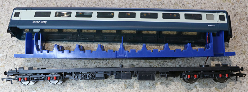
Right, plate flattened and plastics bent back into shape (with a few saw cuts in the base of the seat moulding). Now we can see the lighting module.
The window mouldings are only lightly glued to the upper body shell, below the windows. I've removed them before spray painting. The lighting module (was) held to the roof by adhesive tape and three blobs of flexible glue.
To drop the body shell in order to cover the underframe sides:
First the cutouts below the doors are extended to clear the running board ends.
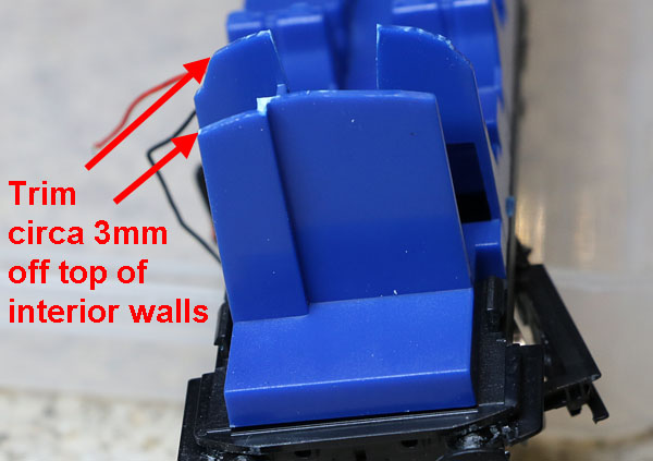
The internal walls are reduced in height.
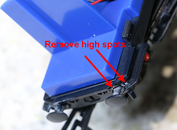
High spots above the rear of the buffers and between the buffer and the running board are removed. The clips to the window mouldings will also need adjustment when refitted.
That's much better!....... but mods to the clip area in the windows and the chassis will be needed to fully hide the underframe sides, when the windows go back in (See below for my solution.)
The lighting board has been modified to increase the spread of the the LEDs throughout the seating compartment. Clipping Mods:
0.5mm plasticard sheet glued to upper body shell clips using liquid poly cement. (This photo in fact shows the corresponding clip in the brake runner coach upper body shell.)
Chassis carved away below the clipping hook. (Allows the upper body shell clip to move down further.)
Chassis carved away below centre clipping hook. (To allow the upper body shell clip to move down further.)
Windows in, clips modified and lights assembly re-installed with inter-car connector.
Lights on. |
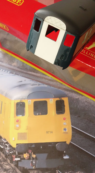
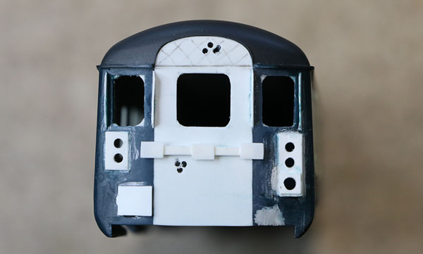
| 3. The DBSO A second open brake Mk2E coach, with lighting fitted is the starting point.....
The unmodified Horby Mk2E showing the problem exposed chassis edge.
Dismantled, ready to start modifications.
Front door plating fitted and windows cut. (corners still need filling)
Side modifications
Ready for the transfers.
Transfers now on, matt varnish applied. Upper flood light brackets in place. Original windows trimmed and refitted. New front window cut and glued in place. Wheel contacts fitted to second bogie and extra liquid gravity weight added above the forward bogie.
Running lights installed I've decided to forget about adding a detonator flash LED to the lead wheel as its a long way from the speaker in the locomotive. (Circuit diagram amended accordingly.)
Programming the DBSO LokPilot FX V4 decoder:
Some of the lights maybe a bit on the bright side, but that can be adjusted via a few CVs:
The Hardware Installation:
Showing the electrics all glued to the roof of the upper body shell. In the chassis, wheel contacts are fitted to both bogies and extra weight is added in an attempt to improve track pick-up efficiency. A sub-miniature two way connector takes the chassis track feeds to the decoder in the upper body shell. The Hornby lighting board has been trimmed to only illuminate the seating area.
Driver in Hi Viz vest (& cap) in the cab. (With the cab light on.)
Windscreen wipers and deflector now added. Having now discovered that the "floodlights" are in reality, infra-red illuminators. I am advised that they do also emit some visible light, which has a purple-ish tint. Something like this maybe? (LED intensity returned to full via CV32=0 + CV278=31, to help penetrate the paint filter)
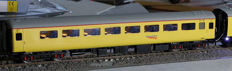
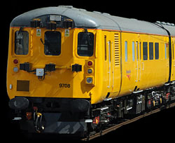
DBSO 9708 at the rear of the test train. With thanks again to Kevin Bates for permission to use his photograph. |
| 4. The
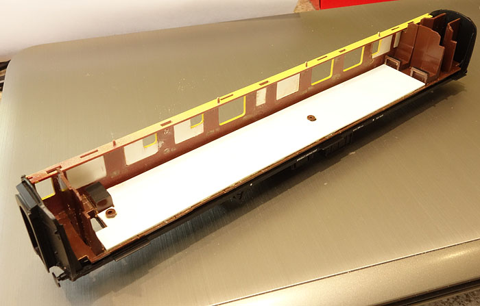
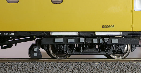
Ultrasonic Measurement Coach A Bachmann Mk1 second open coach is the starting point for the ultrasonic measuring car. (Red & cream livery was the only available choice.) Dismantling the coach required the removal of the two bogies to access the 3 screws holding the seat moulding to the underframe. However, to separate the roof and sides from the base, the three metal wires simulating cables or pipe work at each end of the coach, had to be cut as they could not otherwise be removed. The coach sides could now be unclipped from the roof. Finally, the glazing pieces were carefully pressed out from the side panels, braking the weak glue bonds, in order to remove them (intact).
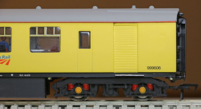
(The side panels had already been modified of course when this photo was taken.) Measurement coach number 999606 is the subject of my model. The side panels were modified in line with photographs of the coach, found on the web. 1mm plasticard was cut to fill in the plated over windows and holes created for new windows and doors. The edges of the new doors were scribed into the plastic and the corresponding edges of the plated over doors were filled and sanded.
Panels completed and ready for spraying.
Side panels sprayed with Humbrol 69 over matt white.
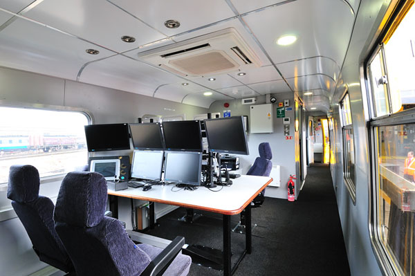
Found on Network Rail's web site..... Inside an ultrasonic measurement car. Judging from the windows, this is probably car 62384. However, I'll use it as an indication of how my car (999606) might look inside.
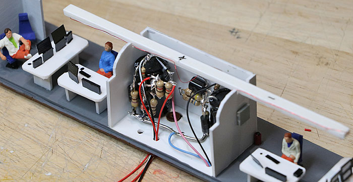
Seat moulding attacked with saw and Stanley knife, to remove the original seats...then carpeted with 1mm plasticard!
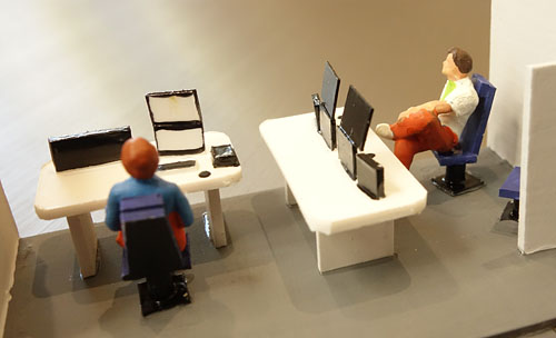
Crew, seats and desks including VDUs ready to fit.
Work stations created on either side of a central electronics bay.
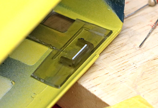
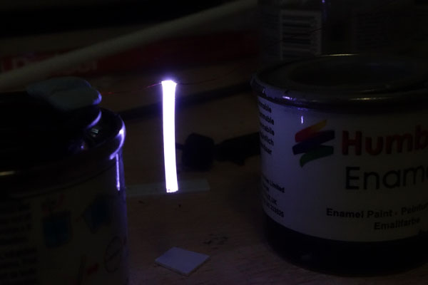
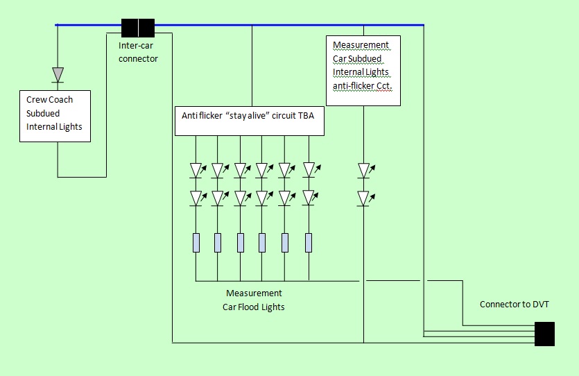
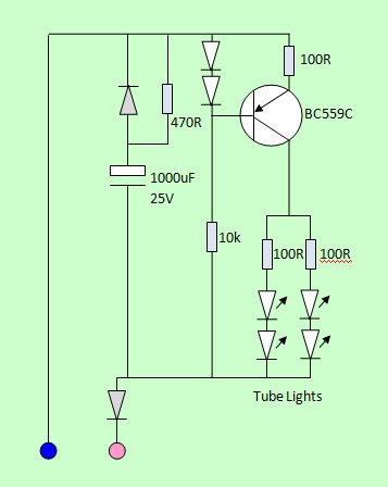
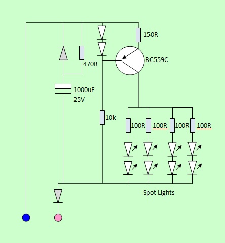
More thoughts re the Measurement car external and internal lighting: External Lights: Looking more carefully at night photos of 999606, there are 4 small floodlights mounted on the underframe around each bogie. (making 8 in all). These LEDs are not hugely bright, so they are expected to draw only a nominal current and will be configured around an appropriate anti-flicker circuit, housed within the underframe boxes. Additionally there are two tube lights mounted on each side of the underframe just inboard of the end doors above the sensor equipped bogie. I'm hoping to use a single white LED for each of these, illuminating a short 1.5mm fibre, painted white at the end and along one side, to reflect the LED light outwards.
15mm length of 1.5mm diam fibre, viewed from the opposite side to the thin white line. (A white chip LED running at 2.5mA is superglued to the end of the fibre.) The LED wires are supported by a couple of Humbrol paint tins, with the fibre dangling below. It works rather better than expected...... Just got to find out how to straighten the gentle curve out of the fibre!
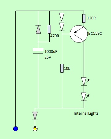
Internal lights: A single white overhead LED will provide subdued lighting to each of the two crew areas. These two LEDs will be mounted on cantilever beams from the central electronics bay, which will house the associated anti flicker circuit parts.
More detail on the anti-flicker circuit(s) below, now I know how much current the LEDs need, to look "realistic".
Small Spot light circuit (4mA total LED current = 1mA per LED). Some minor corrections: The pink wire series diode can be shared between spot & tube lights, whereas the negative feed diode shown on the internal lights circuit is nor required as the feed is derived via existing diodes in the DBSO.
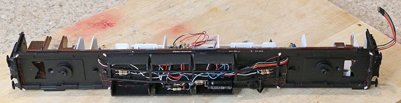
Internal & tube lights anti-flicker circuits hidden in the electronics bay.
Close-up....the circuits are soldered around the two 1000uF capacitors which are glued to the side walls.
The flicker free circuit for the 8 small spot lights surrounding the bogies is hidden within the underside boxes. All exposed wiring and parts will eventually be painted matt black.
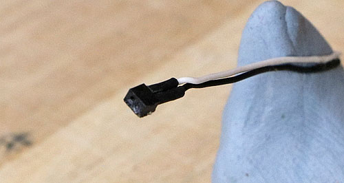
I was testing the circuit operation before final assembly, when I discovered that the crew car connector socket had one port full of superglue.
Not fixable, so remove and replace! New connectors ordered from Digitrains!
Magic! Digitrains delivery of more robust 1301 connectors within 24 hours of order placement! The 1301s are only slightly bigger but a lot easier to reliably glue down, without the superglue finding its way into the socket. Unit tested OK with the crew car and re-assembled. The tube lights have been fitted and tested. I've added some cosmetic mods to represent the ultrasonic sensors and other bogie additions, but as shown below these are fixed to the Bachmann original Mk1 bogies which don't look right at all!
I've ordered up a pair of the Bachmann's later Commonwealth bogies and also a set of B4 bogies. I'll evaluate them with a view to producing a more convincing solution!
Commonwealth bogies replace the originals....still not quite right, but a bit more convincing than the originals. November 2015: Refitting with more accurate Mk6 bogies, sourced from Southern Pride Models:
Now fitted with modified Southern Pride SR Mk6 bogies
The measurement sensor bogie (with added tie-bar etc)
The plain bogie. Photographs of the real 999606 reveal a somewhat shorter bogie with pivot point closer to the end of the car but apart from that issue, these look much better than previous efforts. Recent photos (Q2 2015) of 999606 also reveal a repainted darker gloss yellow colour, with the Network Rail logos shifted to sit under the next window, closer to the sensor bogie...... Its a little late for a re-spray! :-( |
Transfers:
![]()
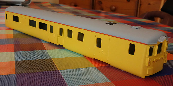
Upper bodies painted with transfers in place. Next job is to apply an enamel matt varnish sealing coat to the yellow areas, so back to the masking tape!
The transfers are from Railtec. The Network Rail logos, overhead line warning labels, other coach end markings and DBSO numbers come from a set covering
the Network Rail optical measurement gauging train. The remaining coach numbers are from a Network rail coaching stock numbers sheet.
The orange cant rails are painted on using Humbrol matt orange enamel with masking tape.
The Ultrasonic Measurement Train Comes together:
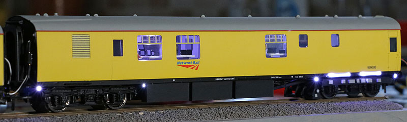
Photos of the NR test trains suggest that most of the mark two coach wheel bearing covers are painted yellow and the door steps have a white edge.... Now in place.
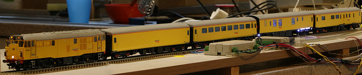
Loco pulling
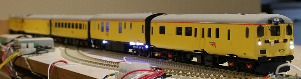
Loco pushing
| Operational
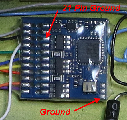
Issues: When operating with the DBSO at the head of train and the loco pushing from the rear, the DBSO lights suffer from a degree of flicker. In order to combat this, I plan to fit 4000uF of decoder "stay alive" capacitance immediately behind the DBSO cab bulkhead. There is no indication in the ESU LokPilot V4 manual of the FX variant pad locations, where I can gain access to the ground line to connect the new parts..... but a bit of probing has identified a group of three pads that seem to be provided for this purpose. One is ground, another is common positive and I guess the third is used if an ESU power pack is to be used. (The FX board includes the 21 pin tracking, which includes a (not easy to access) ground pad, so I just had to confirm continuity between the edge mounted pad and the 21 pin ground track.)
That helps a lot!
Cosmetic Problem: The Bachmann Mk1 coach rides quite a lot higher than the Hornby Mk2Es. (As can be seen in the video.) The Bachmann Mk1 wheelsets are 14mm in diameter.... Much larger than the MK2E types which have a 12mm diameter. I've now replaced the original wheels with Bachmann 12mm wheel sets, taken from their B4 bogies (and adjusted the height of the ultrasonic scanning devices to clear the rails once more). This looks much more like the scale size of the real Network Rail measurement car wheels and the resultant 1mm reduction in overall height brings the Mk1 almost down to Mk2E roof height..... but not quite. This is probably due to my Mk2E mods. which have brought the Mk2 bodyshells down by around 1mm to completely cover the under frame side girders. The net result however, is a definite improvement, and a compromise that I can live with!
Showing the effect of 12mm wheelsets. (Closer but not quite the same height.) Note: This mod had not been done when the video was made. |
Click here to watch a Youtube video illustrating the Test train
Main Suppliers:
|
Supplier (Click for Website) |
Comments |
| Hornby | The Class 31 locomotive was pre-ordered direct from Hornby. |
| Hattons | The source for the Mk2E and The Mk1 coaches used as the starting point for the Measurement Train. |
| Digitrains | Source for all the new LEDs and connectors. |
| DC Kits, D&E Videos | Source for Bif's Class 31 sound project in an ESU LokSound V4 decoder. |
| SW Digital | Source for The DBSO ESU LokPilot function decoder. |
| City Cycle Centre Ely | Source for Humbrol paints and Tamiya masking tape. (Our nearest model shop.) |
| Railtec | The Network Rail, OHL warning label and coach number transfers came from Railtec. |