| Colas Class 37....... |
 |
| Colas Class 37....... |
|
|
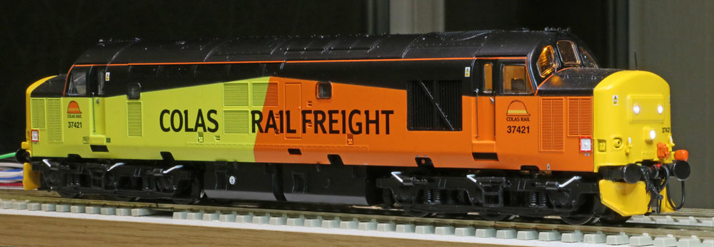
Bachmann's Class 37/4 in Colas livery receives a Zimo based sound system and DCC controlled lighting. |
|
Introduction: The Colas 37 will provide new alternative motive power to haul the Network Rail ultrasonic measurement test train, if the even more elderly Class 31 has to undergo maintenance :-) Paul advises that all being well, a Chetter protodrive Zimo Class 37 decoder will be available soon....So the update planning will assume a Zimo sound solution. Based on previous experience with Bachmann 37s, the speaker will be an ESU 50334 20x40mm unit in its standard enclosure, mounted facing downwards towards the track, in the fuel tanks. |

A DC run suggests that a bit of running in maybe required. The decoder motor control will have to work fairly hard to achieve smooth slow running.
Note: dry bearings on the worm gear in one bogie maybe the problem..... if so, now lubed!
|
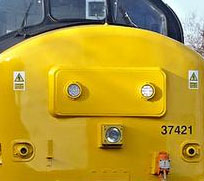
First Issue: The new Bachmann Colas 37 model has yellow marker lights. Looking at 37421 on Google images, suggests that the real loco is equipped with white LED technology markers. So, looks as if I have an additional task: replace the original marker LEDs with pure white types! I hope the lighting boards are accessible! ..........
Major problem! It looks as if I will have to remove the yellow front and rear nose assemblies, in order to access the lighting PCB assemblies. These appear to be securely plugged and glued to the main upper body moulding, so collateral damage looks inevitable. Some annoying compromises maybe necessary!
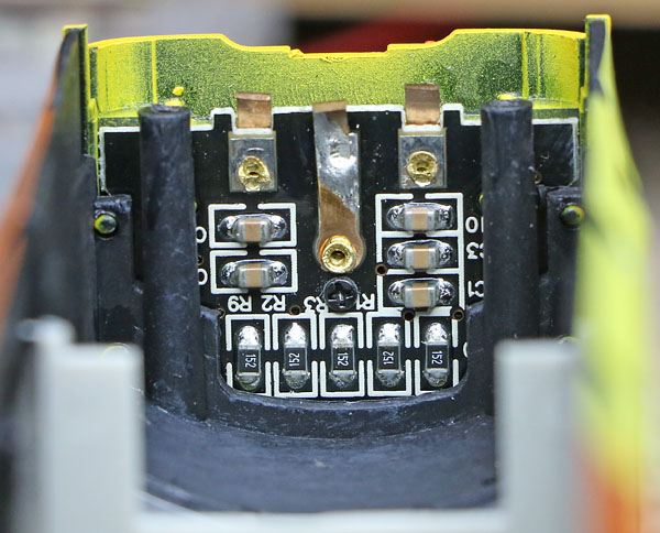
Lighting PCB sandwiched between the nose cone and the main body shell.
But after some very careful prodding and a bit of local levering with a small flat screwdriver:
Access to the lighting PCBs successfully gained with clean breaks!
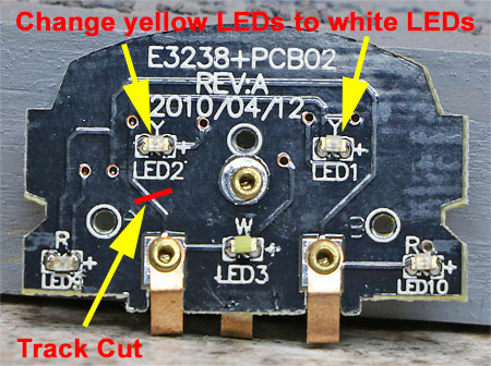
Lighting PCB assembly circuit The new white LEDs are brighter than the original yellow devices, so an additional resistor is required in series with the marker LEDs. |
|
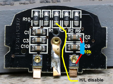
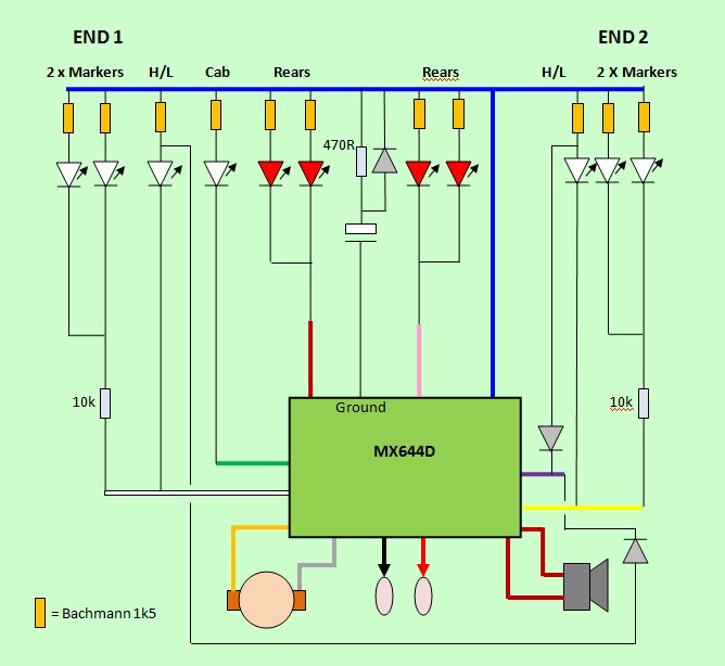
Electrical circuit configuration: A simple circuit is possible, using just 6 of the 10 available function outputs incorporated in the MX644D:
The circuit will look something like this. The headlights can be disabled via FO2, allowing the headlights to be switched off during yard working. An additional resistor is fitted in series with the marker LED pair (10k looks about right to get the intensity down compared to the headlights.) A similar arrangement could be used with a Bif LokSound V4, but N-channel MOSFET buffers would be needed between the Aux3 / Aux 4 and the rear lights. |
|
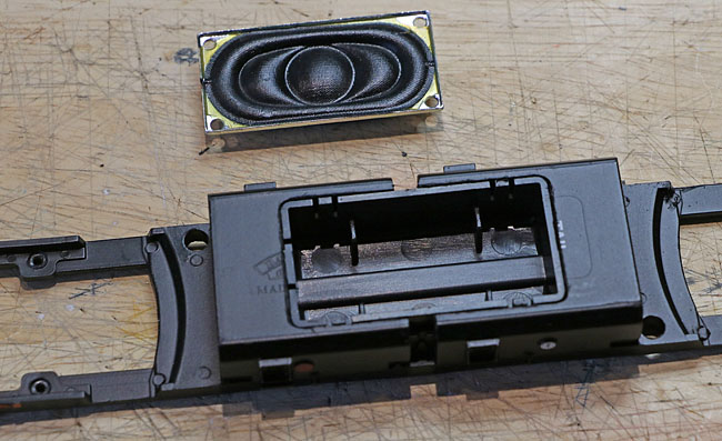
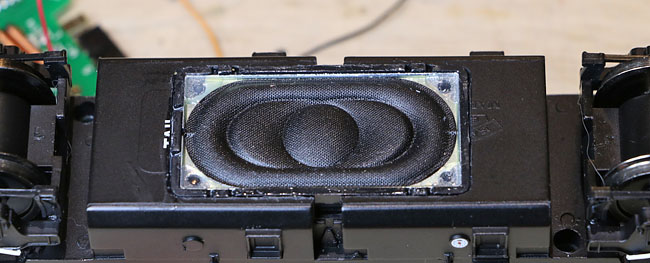
Fitting the speaker: In order to access the inside of the fuel tanks, the chassis assembly has to be dismantled. First the bogies are removed. This allows the underside screws holding the plastic sub-chassis to the cast metal block, to be unscrewed. Finally, the ballast weight within the fuel tank can be removed, together with the now redundant underside switches. There is just room to fit the ESU enclosure within the fuel tank (positioned centrally). This provides an air tight enclosure for the downward facing 50334 20x40mm speaker. This time I've cut a rectangular hole, sized so that the enclosure, with speaker installed, can be inserted through the hole in the tanks underside, from outside.
Enclosure loose fitted in place.....Need a new speaker though, the one in the spares drawer shown above is an old 1 watt type which I initially mistook for a new one. Order is now placed with Digitrains!
Next day delivery by Digitrains! |
|
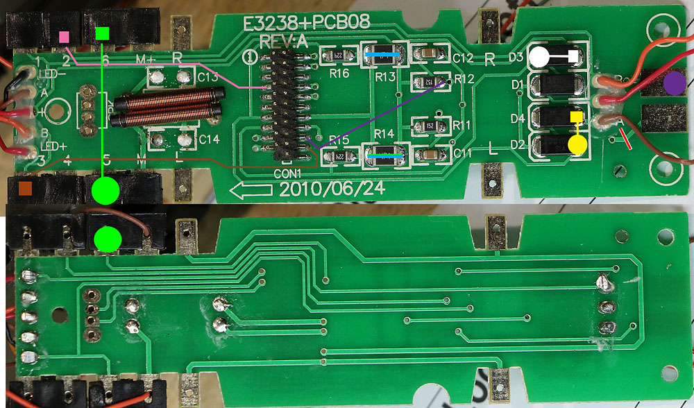
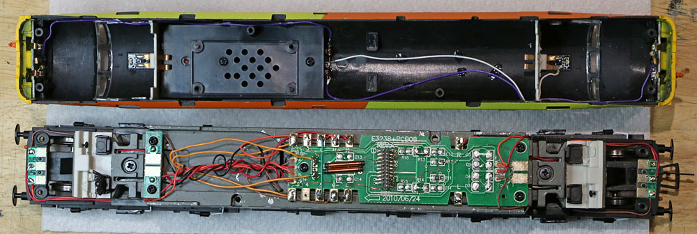
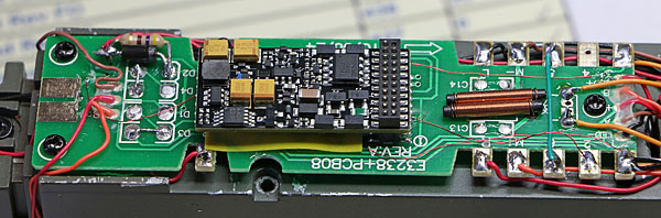
Modifying the main PCB and completing the wiring: First photos of the top and bottom of the main PCB were used to trace the tracks and work out how best to adapt the original PCB to make the required function connections:
In fact, for my DCC only operation, the only surface mount component required was R11, so all the other parts except the series motor coils were subsequently removed. The additional wiring is colour coded to indicate which FO is involved and a track cut is made. The contacts for the cab light in the unmanned cab were instead used to connect to the headlight disable leads via two diodes in the upper body shell.
The modified chassis and upper body shell.
All now ready (I hope) for the Zimo decoder................... |
|
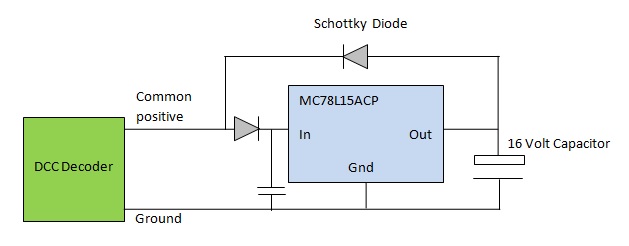
Stay Alive Capacitors: The space available within the Class 37 body work for stay alive capacitors is quite limited. About the only useful volume is in the nose sections. I can definitely get a single 1000uF 25V cap into each end, but I would prefer to double the total capacitance. I've located some physically smaller 16 Volt 1000uF caps that would allow a pair to go into each end..... but 16 Volts is a bit close to the kind of voltages that some DCC systems might throw at the locomotive....... so I'm going to experiment with a tiny low cost voltage regulator, that will protect the capacitors from excessive charging voltages. (The same approach would also offer equivalent protection to super-capacitor packs rated at 16V max.)
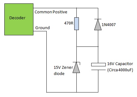
The proposed circuit I've ordered up some parts to try........ Well initial experiments demonstrate a good level of protection against excessive charging voltage.... but when the power is removed and the capacitor takes over, the regulator appears to draw quite a lot of current from the discharging capacitor. I haven't quantified the loading effect yet and if using a super-cap, there maybe sufficient charge to still perform a useful task. However, for conventional capacitors, its not an ideal result, so I'm pondering on alternatives....... Plan B: A simple zener diode approach:
If the charging voltage is below 15 Volts, the zener diode has no discernable effect and looks like an open circuit. However, if the charging voltage exceeds 15 Volts, the zener diode acts like a clamp, preventing the voltage across the capacitor exceeding 15 Volts and conducting any excess current direct to ground. The current through the zener diode is controlled by the series 470 ohm resistor (which also prevents the large capacitor from shorting out the DCC supply). The resistor and zener diode need to be able to handle enough power without damage, to deal with the maximum DCC supply voltage that might be thrown at the circuit. A few simple sums can reveal how much power the two components need to deal with. My application is substituting 16Volt capacitors in a location that I would feel quite safe to use 25Volt types without external protection..... so I'll do the sums to see how much power the resistor and the zener would have to handle if a 25 Volt charging voltage was applied. (Although in fact I know that my own Lenz system will only ever subject the circuit to around 15Volts maximum.) So: If the input voltage is 25, then the voltage across the resistor will be (25 minus 15) Volts = 10 Volts. The power being handled by a resistor of R ohms when it has V Volts across it is (VxV)/R = 0.213 Watts in this situation. The current (I) through the resistor can be found using Ohms law (V= IxR) In this case Current = 0.213 Amps. The power being handled by the zener is voltage x current which here = 0.32 Watts So adding a little contingency, the circuit will be fine at 25 Volts using a pair of 1k quarter watt resistors in parallel to make up the resistor (so actually 500ohm rather than 470) and a zener capable of dealing with say 1 Watt or more. I've got some 1.3Watt 15V 5% zeners on the way. When they arrive, I'll give it a try! Yup! That works fine! With 25 Volts DC applied from a DC PSU instead of the decoder, the parts only get mildly warm and the max capacitor voltage (with the first zener tried) is 15.6V. My Lenz system voltage is low enough to mean that the only exercise the zener circuit would get, is in the case of some freak transient pulse response to a fault..... however, the locos might get used elsewhere, so the use of a low cost zener diode is still justified! |
|
Real world meets original plan: The small 16volt 1000uF capacitors were lost in transit from Hong Kong. Amazon kindly refunded me, but unfortunately that leaves me with only limited immediate options. I've decided to fit a single 1000uF 25V capacitor in each nose section as a temporary expedient. (No zener diode required).
Chassis assembly tidied up, including locally insulated PCB top ready to fit the decoder.
Close-up of capacitor mounted on plasticard shelf. (Clear of bogie at rear and lighting spring contacts at the front) |
|
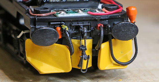
Adding the ploughs (and dangly bits at the front end):
Thanks again to Kevin Bates, for kind permission to use his photo of 37421, which shows the ploughs and other front end detail. (Also confirms the technology used for the front markers!) Fitting the Ploughs: The Bachmann three blade snow ploughs are designed to plug into the bogie coupler socket. But of course, they then move from side to side as the bogie negotiates model rail scale curves.... not at all convincing! The simple expedient solution is to trim the front of the bogie coupler socket (to give clearance) then remove the coupler plug from the plough assembly and glue the plough assembly directly to the bottom edge of the buffer beam. On the rear of the loco, where a tension lock coupler is used for train haul, The outer plough blades are separated from the Bachman plough assembly and individually super-glued to the side of the coupler. These will move with the bogie but fortunately they are a lot less conspicuous than the front plough, particularly when a train is on the hook! Bachmann also provide a variety of hoses and jumper leads, plus a hook with coupler fitting. All the front parts (plus rear hook) now in place with a bit of a struggle!
|
Paul's Protodrive decoder has arrived. Plugged in and ready to go!
|
Programming the CVs : Paul's initial function list, after some minor tweaks. With reserved Network Rail Test Train lighting occupying keys from F22 to F26:
Swiss mapping will be on this basis:
So the CVs will be as follows:
A few other CV tweaks are also required:
All working rather well (understatement)! |
|
The 37 is now running successfully under Zimo control, using the PC Traincontroller software to drive the Lenz DCC system. No hint of the original jerky slow running, so the lubricated worm gear bearing seems to have solved that issue. In fact operation is now super-smooth, with very impressive slow running performance. Paul's Protodrive system is working extremely well (even in its interim state). So, now we have some alternative motive power for the Ultrasonic Test Train! |
|
To watch a Youtube video of the locomotive, please click this line
For the definitive version, I think these might work a little better....
For three power level notches, thresholds: Idle-Notch 1: 1/128 ; Notch 1 to 2: 44/128 ; Notch 2 to 3: 64/128
Or for four power level notches, thresholds: Idle-Notch 1: 1/128 ; Notch 1 to 2: 42/128 ; Notch 2 to 3: 58/128 ; Notch 3 to 4: 74/128
Supplier website links:
|
| Click to return to the Home Page |