|
First, the
Headlights:
Two
issues reduce the intensity of the headlights: a) Inverse square law
loss due to the distance of the source LED from the light pipe and
b) Losses within the light pipe.
The
plan is therefore to truncate the headlight light pipes and bond a new LED with
transparent glue directly to the new end of the shortened light
pipes. If this is not successful, plan B is to remove the remaining
light pipe from the lens and to glue the LED directly to the rear of
the lens..... although this will be trickier mechanically.
The
procedure is shown in the sequence of photos below:
|

Showing the light
pipe windows in front of the cab moulding |
Showing the light
pipe assembly with the cab removed |
|

Extracting the
light pipe assembly from the body moulding
|
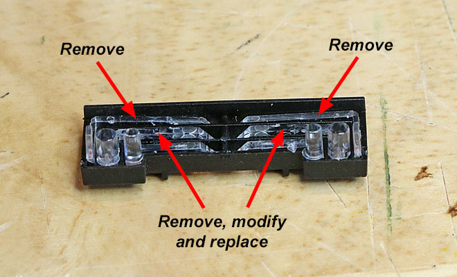
Proposed light
pipe assembly modifications |

Showing a headlight lens
with just the short vertical section of light pipe still attached. The light
pipe was cut using a Stanley knife.
A pre-wired "sunny white"
DCC Concepts Nano-LED is bonded (beaming into) to the exposed end of the
remaining light pipe.
(The lens is held in a
lump of Blu Tack, while the glue dries.)

After the glue has set,
the LED is fired up using a suitable series resistor and DC power supply.
Light leaking out of the
sides of the LED is minimised by careful application of black enamel paint.

Repeating for the other
side. (This LED works fine but has a conspicuous solder blob, which might
explain why the pack contained 7 LEDs rather than the specified 6?)
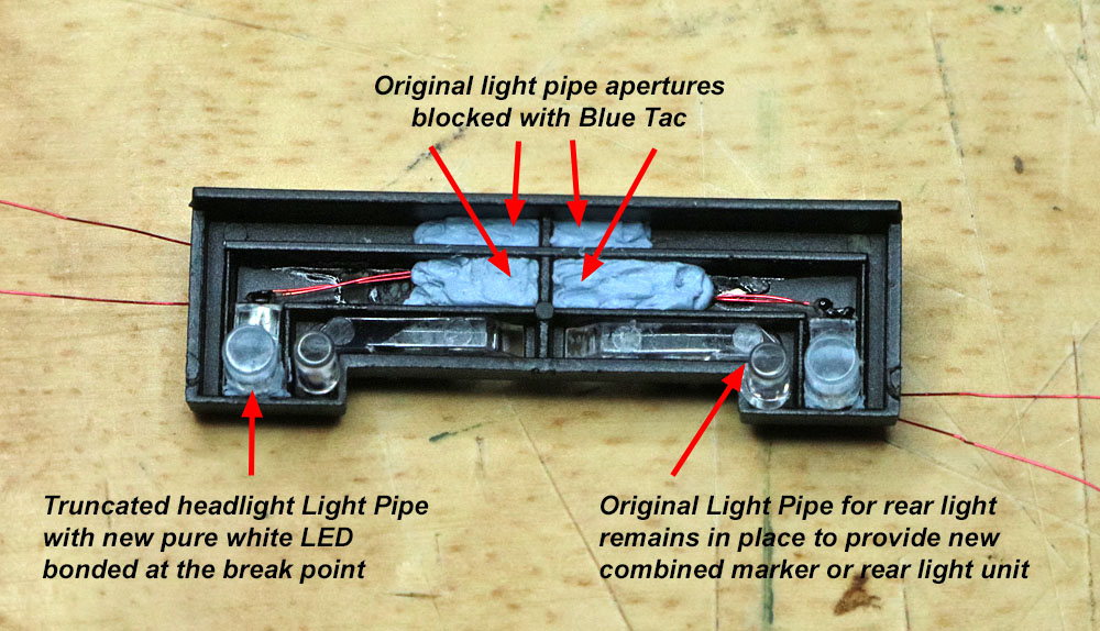
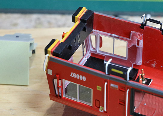
Showing the re-assembled
light pipe enclosure. The LED wires are routed through the old headlight
light pipe apertures in the rear of the enclosure.
Blu Tack is used to block the
now unused light pipe apertures and also to provide temporary support to the
rear of the headlight lenses.

In this photo, the light pipe
enclosures have been re-fitted and cab mouldings re-installed at both ends
of the locomotive.
The series resistors for each
new headlight LED are glued to the inner side of the locomotive roof, and
the interconnecting wires have been added.
|
Next,
converting the original rearlights into dual rearlight / marker
lights:
The
original warm white headlight and marker light chip LEDs are removed
from each of the original lighting boards. A thin plasticard strip
is glued to the PCB just above the original rear light chip LEDs.
Pure white pre-wired chip LEDs are glued to the plasticard
insulator, as close as I dare to the original rear light LEDs. The
new chip LED wires are soldered to the pads of the original marker
lights at the top of the PCB (being careful to get the polarity
correct.)
With
the headlight LEDs now removed from the small lighting boards, there is no
longer any need to re-use the
plastic shroud moulding that was previously fitted over the LEDs, prevented light leakage between the
lamp lenses.
|

Front view of modified
small lighting board assembly
|
Electrical
connections between the new headlights in the upper body shell and
the chassis assembly:
Three
wired connections are made to a small section of solder strip, glued
to the top of the EM2 loudspeaker. The wire length is contrived to
lay along the top of the chassis assembly when the upper body has
been re-fitted.
|

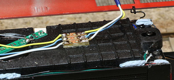
Close-up of the solder
strip
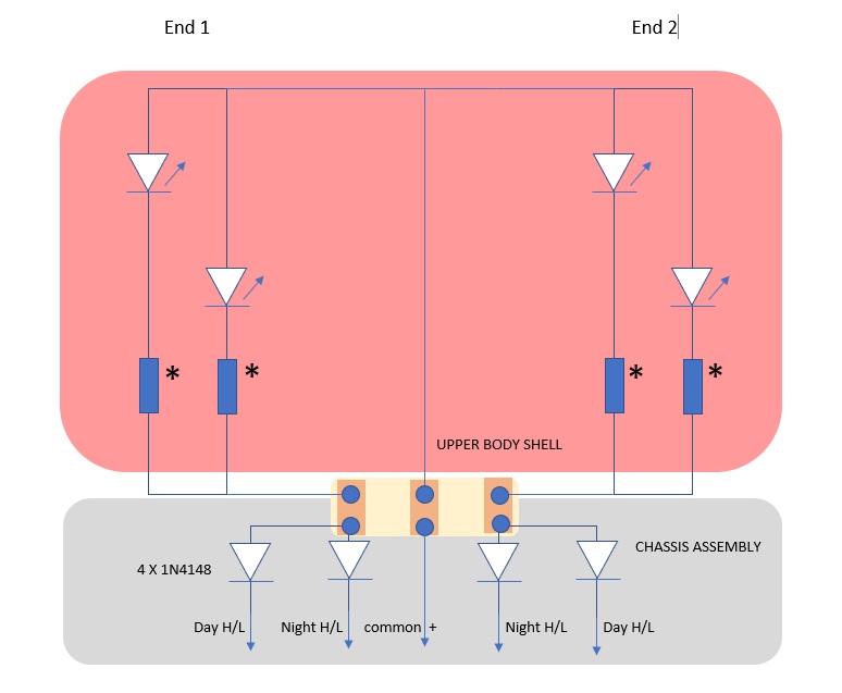
Headlight LEDs electrical
circuit..... Resistors marked *
are between 2k2 and 4k7, selected for equal brightness.
|
LokSound V5
settings for main beam and dipped beam headlights intensity:
The
main beam function output level CV is set for maximum intensity (31) and the
dipped beam CV, to 6. The views below show the head-on results,
illustrating that the headlights are significantly brighter than in
Hatton's original arrangement.
The
new marker lights and original rear light LEDs successfully share
the new dual purpose marker / rearlight lenses. (The original
rectangular marker light apertures were subsequently filled and
painted black.)
|

Dipped Headlights |
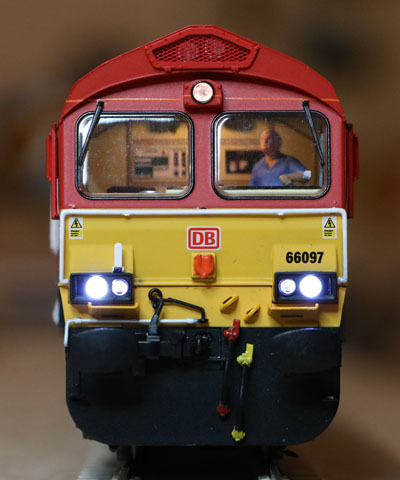
Main Beam
headlights |
|
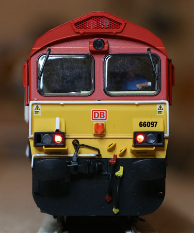
Rear Lights |
|
Stay Alive
Super-cap:
To
improve reliability, I've added a 6800uF AVX supercap, sourced from
YouChoos DCC. These devices are rated at 15 volts maximum, which is
often exceeded on DCC layouts...... So to be safe, I always fit a
series resistor and zener diode to prevent the charging voltage
exceeding 15Volts. Having just used up my supply of 14 volt 500mW
zener diodes, this time I found some low cost 5V6 and 9V1 zeners on
Amazon. When connected in series, a pair of these limit the voltage
seen by the supercap to typically around 14.7 Volts, which works
very well. I glued some thin plasticard to the top of the supercap
just in case it comes into contact with the roof mounted components.
|
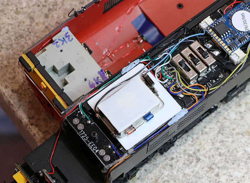
Supercap circuit glued
to a plasticard deck, bonded to the chassis block. Electrical
connections
are made to the common
positive and ground solder tabs on the decoder.
|
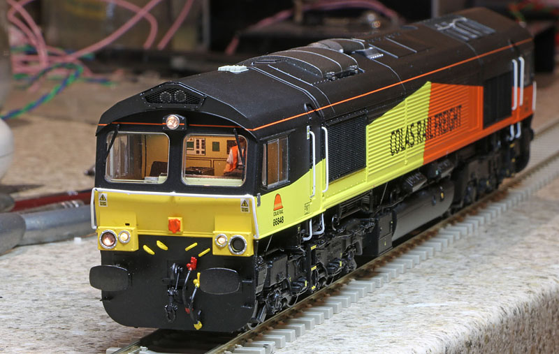
A decision on
a possible livery update:
The
red bodywork colour is painted. It is not the colour of the
plastic moulding. I'm not confident about a clean removal of the original DB Schenker logos without collateral damage to the red paintwork,
without an appropriate touch-up paint supply, so despite obtaining
DB transfers for the job, I've decided to leave the current DB
Schenker finish in place.
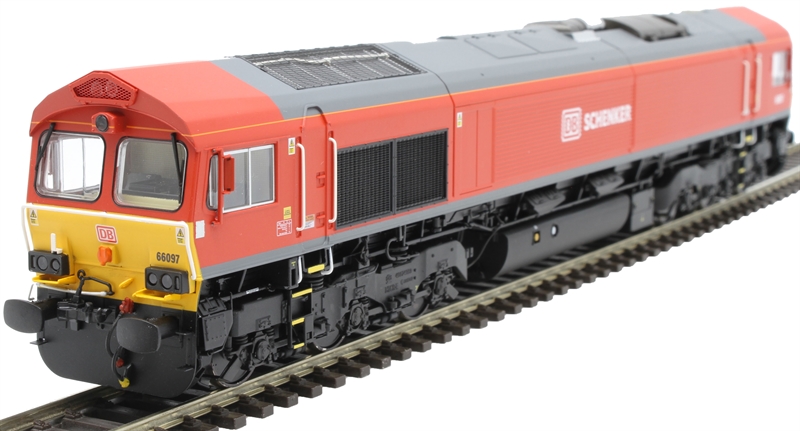
|

The finished locomotive