Updating the Hornby Class 67 with a Zimo based sound system
| Introduction: The availability of a new Zimo based Class 67 Protodrive sound system from Paul Chetter is an opportunity to upgrade the Hornby model once again. This is also a chance to refine and simplify the somewhat "over the top" original interface circuit between the Hornby negative ground lighting boards and the decoder. |
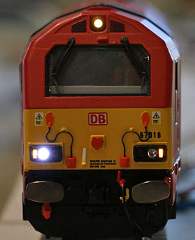
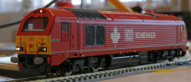
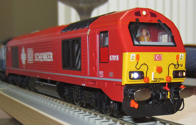
Hornby's 1/76 scale DB Schenker all-red Class 67 number 67018
| Revised Circuit
Proposal:
Hornby use their well known common negative approach to the lighting PCB assemblies. So I have to use a pair of inverting PNP transistors (BC559C or similar) to enable the decoder function outputs to control the positive feeds to the Hornby boards. A pair of diodes (1N4148 or similar) connected to FO3, are used to disable the rear lights when the locomotive is pulling a train. (When FO3 goes negative, the diodes starve the rear light LEDs of voltage). Cab LED and detonator flash LED are connected to the decoder via their series resistors in the normal way. The night time running light switching lines are paralleled and driven via FO1, with a 100k pull-up resistor to hold the Hornby MOSFETs on in daytime operations. (If I had used this arrangement with the earlier LokSound V4, There would have been no need to add the extra FL4 function decoder!) |

MX645 diagram showing the location of the connection pads needed for this project.

Additional wires soldered to the decoder.

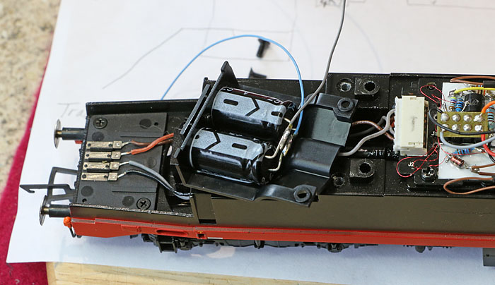
Original DCC interface circuitry on main board replaced with the new decoder circuit. (Less detonator flash LED at this stage.)
It looks a bit of a mess! Key question is: Will it work?
| Initial
Mechanical and sound checks: The loco chassis assembly was checked before fitting the upper body shell, to check basic operation and investigate the sound system. First, to check communication and make sure we don't damage the speaker: Before we fire it up...... master volume is: CV266 Default 65 is max ......reset to this to 25...... O.K. Check basic motor control..... Looking good! ........ Activate sound.... Excellent. All appears to be working OK...... except for occasional brown-outs. Track and wheels cleaned, much better, but I think some stay alive capacitance would be prudent, but where to put it? Ah Ha! Room for 2000uF under the plastic cover over the number 1 end bogie (marked with a white number one in the photo above.) Unfortunately the corresponding number two end cover is a metal casting which protrudes too far down to leave room for capacitors behind the plastic side grills, fixed to it. 2000uF is not really big enough to make a huge impact, but it is certainly better than nothing!
Two 1000uF 25V capacitors connected in parallel to provide 2000uF of stay alive capability.
No more brown out incidents since fitting the caps!
Adjustments to movement related CVs: Operation is smooth, without any obvious judder or hesitation effects, but starting seems a little abrupt in train pulling mode and extremely abrupt in light engine mode, so an increase in CV3 looks a good idea. slowing down seems rather abrupt in light engine mode (with brakes not really required.) So a slight increase in CV4 and more dramatic adjustment in the difference between train pulling and light engine momentum effects also seems desirable (via CV390). High value CV3 & CV4 enables me to enter step speed changes when operating under PC control. This may not suit everyone!
|
| Re-Programming the
Decoder Function Mapping:
Sound Key assignments:
Note: The data in the table below was established by reading the appropriate CVs from my decoder and maybe specific to that device. If viewers wish to remap a similar 67 project, then please read the necessary CVs in your own device, the values may well be different from mine!
Some sound slot volume levels were adjusted to increase relative levels and the updated values are quoted above. All working well !
Swiss mapping for lights control: The Lighting Function Outputs will be controlled using ZIMO's "Swiss Mapping". The following table outlines the content of each group:
These will be assigned to keys 21-25
CV Values are tabulated below:
Groups 1-4 working well ! (Additional hardware needed for 5.) |
|
|
|
Locomotive on the test track with the upper body shell now back in place.
Full Function
Listing:
I may reshape this to maximise commonality with the 66s later......but this will do fine for a bit of video work! |