Hornby Class A2/2 Thane of Fife


During WW2, Gresley 2-8-2 P2 class locomotive number 2005 "Thane of Fife", was transformed under Mr. Thompson's direction into a rather less attractive 4-6-2 pacific configuration which became known as Class A2/2. In the late 50s the locomotive, now BR number 60505,  was based at Peterborough New England Shed. This Hornby model is about to receive a DCC sound conversion:

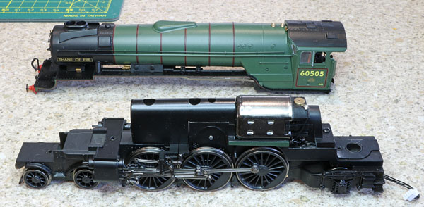
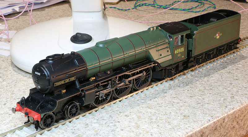
The new locomotive, straight out of the box.


Background:

Despite the RA9 route availability rating, we have been advised that in extreme circumstances, ECML locomotives of this axle loading did occasionally run on the March to Cambridge loop line, via Histon village. 60505 was based at nearby Peterborough and so was more likely than most to have made an occasional sortie along the line, taking great care to minimise driving wheel hammer blow forces while crossing the River Ouse bridge. This was the most fragile piece of infrastructure on the line and I believe was largely responsible for its RA7 rating.

Thompson's A2/2 design had a key weakness in the design of the frames at the front end of the locomotive. Inadequate frame rigidity in the vicinity of the cylinders, resulted in continual failures of joints and components in this area, until substantial frame reinforcements were eventually applied. The locomotives also suffered from poor adhesion and consequent wheel slip in wet weather.... unlike their original sure footed P2 initial design..... but to be fair, P2 crank axle failures, pony truck and worn conjugated valve gear problems were eliminated on the re-worked locomotives, so although not as elegant as their Gresley and Peppercorn stablemates, once the frames were strengthened, the design was not a total disaster.
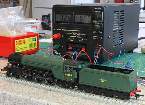
 

DC Testing:

(The current meter reading went up a little when I actually connected the PSU to the rails.)

The locomotive is a fairly smooth runner in DC configuration, straight out of the box. Slow speed running is quite reasonable for a Hornby steam loco under DC control. Using my bench power supply which provides pure DC, the motion is virtually silent at slow speed, but there is some cyclic speed reduction when running really slowly. I hope the DCC decoder back emf load compensation system will be able to deal adequately with this situation, which may also (wishful thinking?) improve as a result of running in.


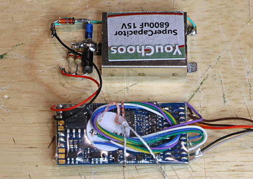
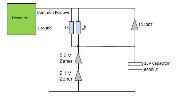
DCC Sound Configuration:

The plan is to install an ESU LokSound V5 decoder with a Locoman A3 sound file. A twin dynamic drive 4 ohm speaker and an AVX 6800uF stay alive supercapacitor, with charging voltage protection, will complete the fit. All these items will be accommodated within the tender. Additional ballast weight will be fitted into the tender if at all possible. So much for the plan, next challenge is to dismantle the tender..... and then we'll see if the plan is viable :-) 

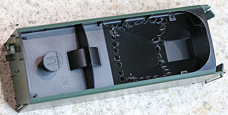
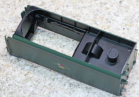
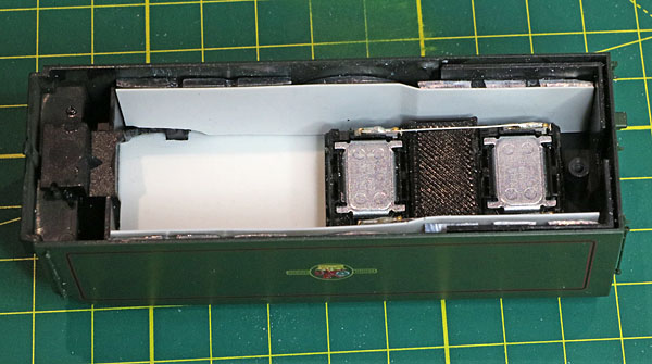
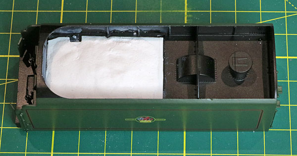
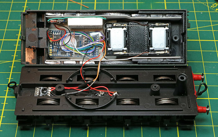
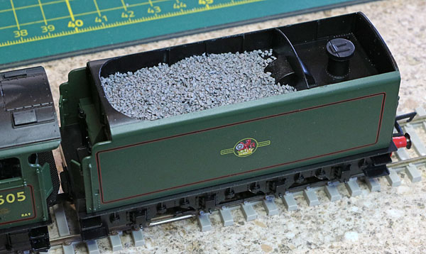
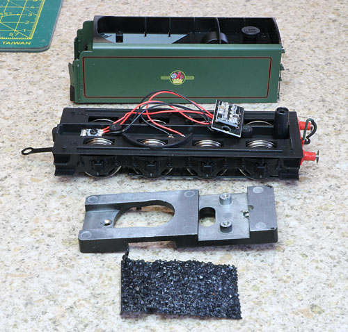
Inside the tender:

The fixing screw is hidden by the rear coupler, which must first be removed.

A lowish dummy coal load can be extracted from the coal hopper, but to fit everything in, I will probably have to construct a new coal level, closer to the top of the tender.

A ballast weight doubles as a 28mm round speaker carrier and 8 pin DCC socket holder. This will also have to be removed and custom ballast added in any spare space.

Build problems:

When the tender top and its chassis were first separated, it was apparent that the screw that should have been clamping the four way electrical socket to the chassis was loosely in place, but as soon as the ballast weight was removed, it fell out. (The shallow thread was stripped and I had to fit a longer screw to secure the socket assembly.) Also two of the wires had been trapped between the weight and the plastic speaker ridge on the chassis. The copper core of the black wire was exposed, if the red wire had also been penetrated, the consequent short circuit would have disabled the loco.

The well publicised rear facing water scoop moulding was also removed and glued back in place in the correct forward facing position.

Wiring and loose screw problems. The screw in fact popped out again when I next attempted

to re-insert the loco plug into the tender socket. I had to replace it with a longer screw.


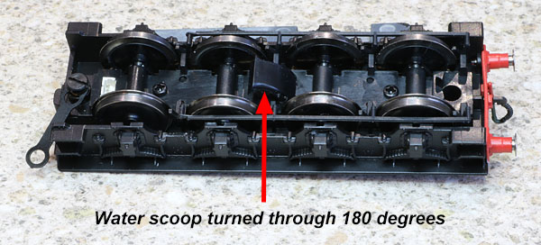
After correcting the water scoop orientation


Motor suppressor capacitor hunt:

 Any motor suppressor capacitors found within the locomotive (or tender) will be removed as they compromise DCC BEMF performance.

Not an issue. No capacitors found inside the locomotive.


Lighting:

Initially, the model will not be equipped with working lights. (Discs will provide the head codes). In future DCC Concepts LED lamp(s) may be added to the front lamp irons and flickering firebox LED(s) may be installed. Although this will require an additional 3 wires between tender and locomotive and my traditional miniature connectors for this purpose seem to have ceased production, so I'll review the situation when the DCC sound system is up and running.

Plenty of room for firebox LEDs and a straightforward path for extra wiring to the tender.

Wire routing for front lamp(s) will be more of a challenge!


Tender Plastics Modifications:

The internal coal hopper has to be removed to make room for the electronics. First a sequence of holes is drilled close to the periphery of the plastic to be removed (with a small power drill). Then the Stanley knife is used to cut through gaps between the holes. After the unwanted plastic is removed, the knife is also used to expand and straighten the edges of the hole.

Initial holes drilled.


Unwanted plastic removed. (A new coal load will eventually hide the new space.)


Lead curtain hem weights, cut in half and super-glued to the tender inner sidewalls.


Insulating plasticard super-glued over the new lead ballast weights.

Speaker and replacement coal load roof super-glued to the tender top.


Polyfilla shaping for new coal load


Locoman LokSound V5 and stay-alive AVX supercap with its charge voltage limiter.


Stay alive circuit showing simple voltage limiter


Decoder and stay alive bonded in position.


All wired up and ready to run (I hope).


Coal simulating ballast chips glued to the new hopper lid (prior to painting matt black).


Coal painted with thinned matt black.


Optimising the Decoder Motor Control:

The A3 sound project is as close as I could find to what I imagine a Thompson A2/2 would have sounded like. However, not surprisingly, the original Locoman LokSound V5 motor control and chuff rate CV settings (which I guess are OK for the Hornby A3 model) required a bit of a tweak to optimise performance and achieve the classic 3 cylinder 6 chuffs per driving wheel revolution on the A2/2.

Initially, slow speed behaviour was a bit jerky, so I've adjusted CV51 & CV52.  The loco barely moves on the minimum speed step, but runs reasonably smoothly on the next speed step. Moving CV2 up from 1 to 2, speeds up the minimum speed step, but makes initial acceleration a little too abrupt. So I've kept CV2 at 1. The chuff rate was a bit trickier to get right due to interaction between the two adjustment CVs 57 and 58. The remaining CVs have so far been left as they were, pending higher speed trials on the loft layout (which may lead to further adjustments....). The original settings are shown in dark blue and adjustments are shown in red below. Any further tweaks that follow will also be re-entered in red.

The loco was a little too lively at high speed in the loft layout, so I've wound down the maximum speed a little by dropping CV5 from 240 to 200 and slowed acceleration a little more by changing CV3 from 155 to 220.

CV Value
2 1
3 220
4 155
5 200
9 40
51 5
52 15
53 110
54 50
55 24
56 255
57 120
58 105

Locoman's speed control characteristic, with a brief exponential rise from stationary, quickly transforming into a linear slope up to maximum speed, is retained.


Add-on parts (brake rigging, cylinder drain pipes, front steps and coupler bang plate) glued in place.

Nice to see that Hornby have designed the transparent box packing plastics to have clearance for the cylinder drain pipes this time!

(I've previously had to attack them with the Stanley knife to prevent disaster, prior to storing Hornby locos back in their box.)


The A2/2 Video....

Click here to watch a YouTube video of the A2/2 on the loft layout


d

Supplier website links:
Hornby Trains    The A2/2 was sourced directly from Hornby.
Locoman Sounds    Source for Locoman sound project on ESU LokSound V5.
YouChoos DCC    Source for stay alive super-capacitor.


Click to move back to Index Page