|
Windhoff MPV Track Maintenance vehicle: Produced by Bachmann in Network Rail Livery
Adding Night Headlights and DCC
|
|
|
Windhoff MPV Track Maintenance vehicle: Produced by Bachmann in Network Rail Livery
Adding Night Headlights and DCC
|
|
|
Introduction: Another end of line bargain from The Monk Bar Model Shop in York! The plan is to add night headlights and fit an ESU LokPilot V4 displaced during a recent sound project. Adding sound is a future possibility, but the initial objective is to sort out the lights and maybe add additional working spots and warning strobes. |
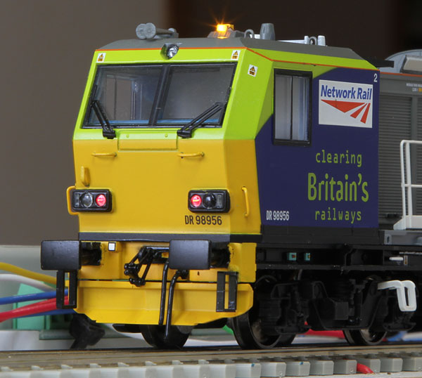
The trigger to my new purchase, photographed at Ely station, on a rail journey to York.
|
Exploring the structure of the Bachmann model: The equipment modules mounted on the Windhoff units, have small plastic mounting studs fitted to their underside. On the trailer car, the mounting flatbed is a plastic moulding and after careful alignment the modules can be successfully pushed into place and remain reasonably stable unless deliberately removed. However, many of the location holes drilled in the metal flatbed of the power car did not correctly align with the module mounting studs. The offending holes had to be drilled out to achieve a successful fit. The power car underside cover can be removed to gain access to the motor and drive shaft. The lighting supply and wheel pick-up tracks to & from the decoder run on either side of the motor on thin PCBs. An area adjacent to the motor is available to accommodate a loudspeaker. Small holes are drilled in the underside cover below this area to enable the sound to escape. The cab assemblies are held to the chassis by 3 small screws. |

Access to the power car underside
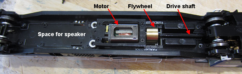
Drive components revealed
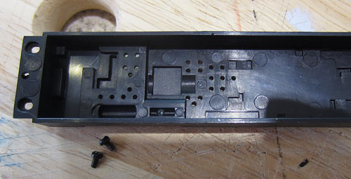
Speaker holes in the lid (look a bit on the small side!)

Cab fixing screw locations
|
The Lighting Arrangements of the Bachmann model: Most of the lighting LEDs are mounted on a PCB assembly attached to the chassis, under the cab, beaming through lenses in the cab front. The exceptions are the top marker lights, which are mounted (with their series resistor) in the cab roof. All the forward LEDs are yellow surface mount types. The right hand day headlight and adjacent marker light lens are both illuminated by a single LED. No night headlight is fitted, although a dummy lens (which does not penetrate the cab front) is mounted in the appropriate location. The rear lights are red surface mount LEDs, beaming through clear lenses in the cab front. Plastic shrouds prevent LED light reaching the wrong lenses. The lighting circuit uses a common positive supply rail in the power car. Two switched function outputs provide negative voltage to either the day headlight and marker lights or the rear lights. In the trailer car, four diodes are used in conjunction with the two function control lines to achieve the same result. A four way electrical connector is incorporated in the coupler between power and trailer units. Two ways connect the wheel contact lines in each car together, while the other two ways carry the light switching lines. |
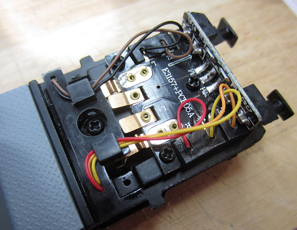
Power Car Lighting PCB Assembly
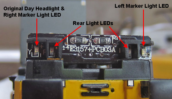
Front view showing the lower LEDs
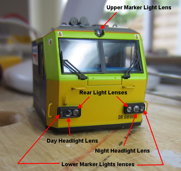
Lighting Lenses mounted on the cab front
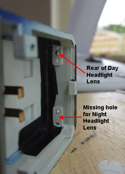 Showing solid plastic behind the night headlight lens |
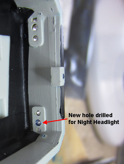 Soon remedied! |
|
Original Power Car Lighting PCB Assembly Circuit
EMC capacitors are omitted |
|
The Proposed New Lighting Arrangements: Holes have been drilled behind the night headlight lenses to enable these to be made operational. Thin plastcard shroud pieces will be positioned to confine the light from the current yellow marker light LEDs to the small rectangular end lens pieces. New chip LEDs will be mounted directly behind the day & night headlight lenses, on the new shrouds. The circuit boards will be modified to accommodate isolating diodes and new control wiring as shown below. An ESU LokPilot V4 decoder will be used in the power car. This will control the power car running lights and new flood lights (white chip LEDs fitted to the spray module at the rear of the car). A separate TCS FL4 function decoder will be fitted in the trailer car, to control the running lights and new strobe warning lights which will use amber chip LEDs mounted on the cab roof. The two original lighting control wires between the cars that become redundant, will be used to feed the strobe signal to a second amber strobe LED situated on the power car cab roof. |
|
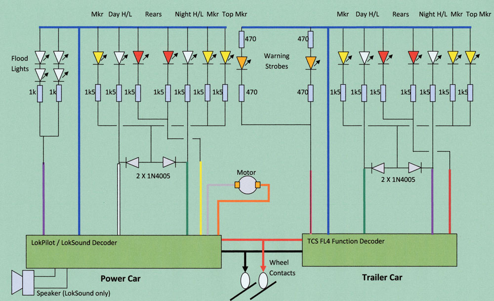
Circuit Diagram with updated lighting
The updated arrangements use two decoders to provide independent control of forward and reverse, day or night running lights in the two cars. Flood lights and warning strobes are added. The wheel contact connections for each car are coupled together and fed to both decoders. The motor is driven from the power car decoder. |
|
Modifying the Running Lights:
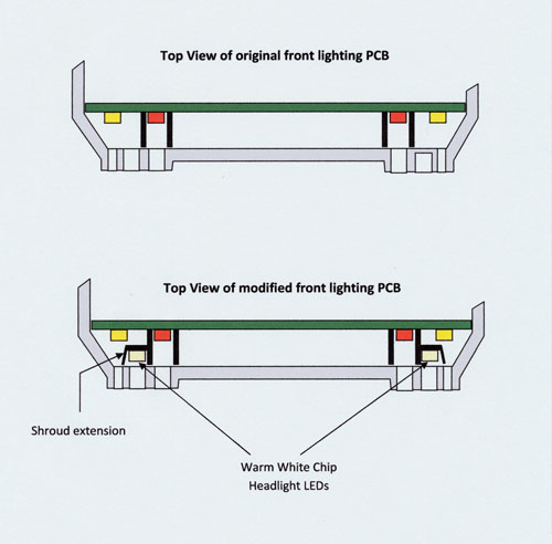
Showing how the new headlight chip LEDs and shroud extensions are fitted
The shroud extensions are made from thin plasticard and painted gloss black to prevent marker light leakage into the unused headlight lens.
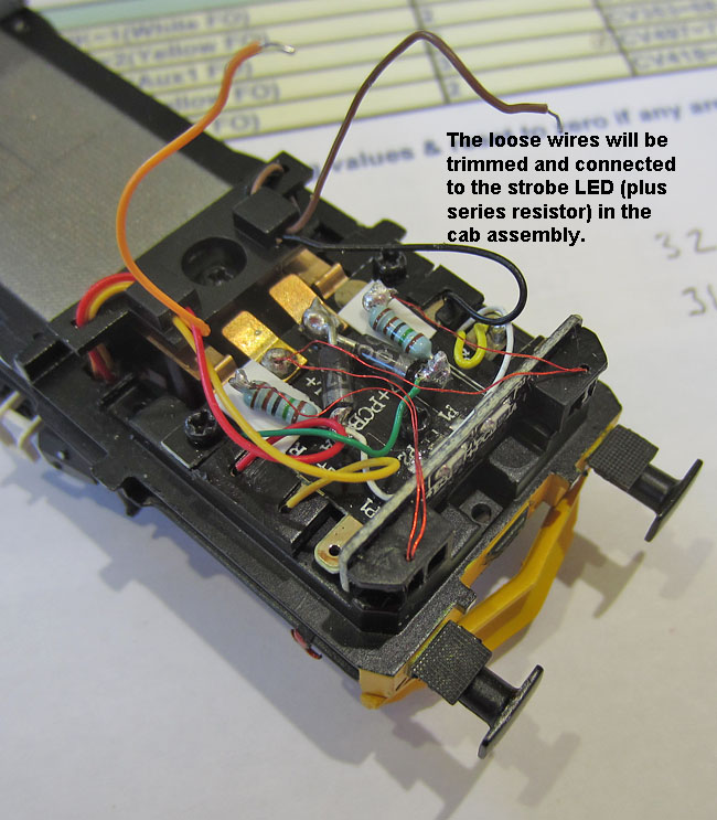
Close up of the power car lighting PCB assembly
Showing the diodes and headlight series resistors (functional but not pretty) |
| Circuit Changes: The model is only going to be used in DCC layouts. This makes most of the Bachmann circuitry on the power car decoder board and on the trailer car lighting support board unnecessary. Without a lot of track tracing, I don't know exactly how the Bachmann circuit operates. To be safe I will therefore remove all the SMD parts and add links where required to make the essential connections between the 21 pin decoder connector, the track contacts, the lighting PCBs and the motor. I also need to add 21 pin connector Aux1 and Aux 2 function output wires, which are not included on the original PCB. Interesting! I haven't found a track connected to the decoder common positive pin...... looks as if maybe the positive connection for the lights was derived directly from the track connections via the on-board diodes. I'll just link directly to the 21 pin connector and drive the modified lights in the conventional way (as shown in the circuit diagram).
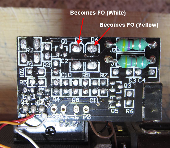
Changes to the Decoder PCB: All SMD components are removed, leaving just the two coils in series with the motor. The motor connections and track contact connections still route correctly to the 21 pin connector. The White and Yellow function outputs are accessible on two pads on the rear of the PCB. Three new link wires are needed as indicated below. The speaker contacts at the bottom of the PCB still connect to the appropriate decoder pins.
21 Pin Connector side: New links are needed for Com +ve, Aux1 and Aux2 to the pads indicated at the bottom of the PCB.
Other Side: The Pads indicated become the White and Yellow Function Outputs
|
|
Programming the Power Car LokPilot Decoder: The wiring connects to the function outputs as follows: White : Right Hand Day Headlight. Aux1 : Left Hand Night Headlight. Yellow : Rear Lights. Aux2 : Flood lights on the spray Module. The control buttons are as follows: Button Zero: Day running (Day headlight fwd; rear lights bwd). Button 1: Night running (Night headlight fwd; rear lights bwd). Button 5: Floodlights on spray module. (Button 6: Strobe warning lights on FL4 decoder in trailer car)
Additionally, other CVs in lines 5,6,7,32,11 and 12 will be checked for earlier programming values & reset to zero if any are found........ That'll teach me! I forgot that the LokPilot defaults are very different from LokSound, even though the function mapping process is similar...... Just took me quite a while to find the programming line that also fired up the floodlights in night running reverse operation! The offending CV is now reset to zero! If I'd checked the defaults first, I'd have found it straight away. |

Spray module side floodlights switched on via button 5 (They are on both sides).
The series resistors are mounted on a small plasticard mount inside the module.
(I'll tidy up the wiring later.)
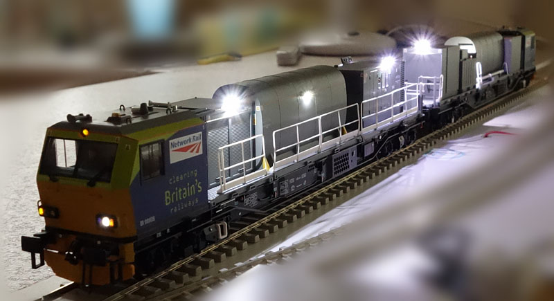
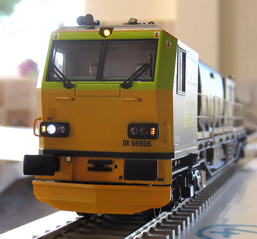 New Day Running Lights on Power Car |
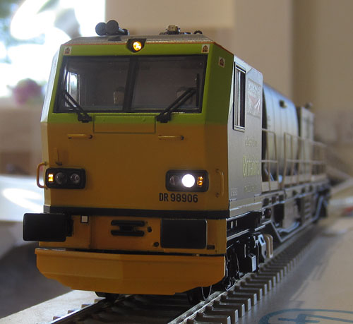 New Night Running Lights on Power Car |
Moving on to the Trailer Car:
|
Programming the Trailer Car TCS FL4 Decoder: The wiring connects to the function outputs as follows: Green : Right Hand Day Headlight. Purple : Left Hand Night Headlight. Brown : Rear Lights. Pink: Strobe warning lights. The control buttons are as follows: Button Zero: Day running (Rear lights fwd; Day headlight bwd). Button 1: Night running (Rear lights fwd; Night headlight bwd). (Button 5: Floodlights on power car spray module.) Button 6: Strobe warning lights.
|

No underside box on the trailer car, so the FL4 decoder is glued out of sight under the chassis.
| Strobe warning lights: Amber double strobe warning lights are mounted on the roof of both cabs, driven by the FL4 decoder in the trailer car.
Showing a strobe warning light before painting, glued to the trailer car cab roof.
The series resistor is split to provide fixed anchor points for both supply wires. 470 ohm resistors are connected on each side of the LED and are glued to the inside walls of the cab.
One of the 470 ohm series resistors glued in place & soldered to a LED wire. |
| Cosmetics: The strobe housings were painted yellow and the visible enamelled wire on the cab roofs and the spray module roof were painted grey. Finally, the coupling hardware, brake hoses and access steps were super glued to the front of each car.
Trailer Car now fitted with the "add-on" bits. (I've since re glued that white step down a little!)
|
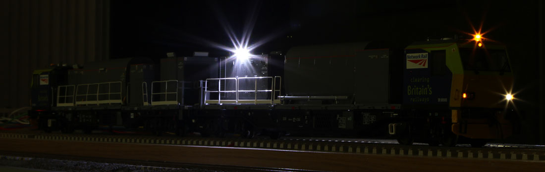
Nocturnal operations are quite normal.
Adding Sound.........
| Adding Sound: I found a Youtube video demonstrating the Howes LokSound decoder with the MPV on a rolling road....... The motor sounds, warning sirens and spray sounds should add quite a lot to the entertainment value. So the next job is to order a Howes decoder, fit a speaker and work out the CV programming changes needed to combine the lights and sounds. |
| Fitting the speaker: An ESU 50334 40x20mm 4 ohm speaker was mounted within the the under-floor box of the power car. The bottom of the moulding is heavily contoured with the shape of the rear bogie motor drive components. Some surgery was therefore required to achieve a suitable flat flush speaker location. A simple thin plasticard frame was then added on the inside, to mount the edge of the speaker, ensuring adequate clearance between the speaker cone and the remaining parts of the floor below the speaker. The speaker was glued and sealed in place using "Glue 'n Glaze". There was not sufficient room to include the standard speaker enclosure. Instead, an air tight seal was created around the speaker rim and the air gap between the box and chassis was minimised, converting the under-floor box into a semi-sealed speaker enclosure.
Speaker installed in power car under-floor box. |
| CV Changes required to
combine lights and sound: The night running lights will be shifted from button 1 to button 2 to avoid disturbing the standard sound start-up button on Bryan's Howes LokSound decoder. This is the only FL4 change. Several further LokSound CVs will be altered to free up buttons 2, 5 and 6 and to separate the motor control adjustment buttons from those used to select light and sound options. I'll complete the table below when I receive the Howes decoder and I can identify the sound slot numbers. Howes LokSound Decoder:
TCS FL4 Decoder:
All lights and sounds now working as planned:
LokSound Motor Control CVs: A few tweaks thought useful here, although some of the figures are as received:
Still a slight wobble at some medium speeds..... probably a need for further running-in. |
| Computer Control: The Windhoff mpv data is now entered into the locomotive listings on Traincontroller and a simple test schedule for a test track video is in place.
|
A New Mini-Project is described below............
Adding some serious floodlighting for night operations:
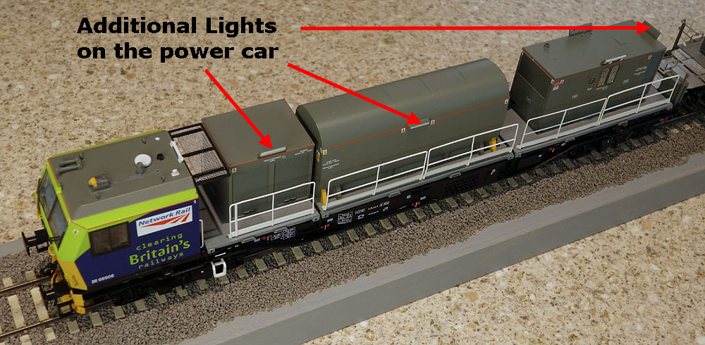
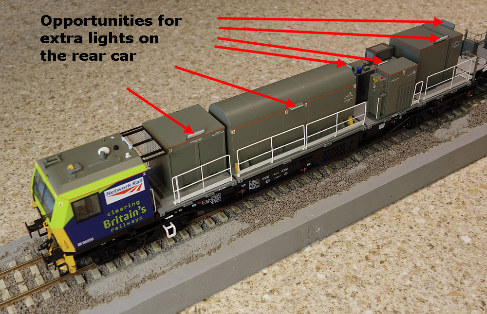
Although the initial pair of floodlights work well, it seems that the real mpvs are significantly more spectacularly illuminated when on night operations. The photos below show additional opportunities for mounting floodlight LEDs:
| Control of the new lights: The power car LokSound Aux2 Function Output (plus common positive) powers the existing floods. A series string of 2 LEDs with a common series resistor of 1k can be connected in parallel with the existing Aux2 load, plus a dimmer single LED (+ 4k7 series resistor) on the side of the water tank. A triple LED + 560R string, a double LED +1k string & a single dimmer water tank LED + 4k7, all wired in parallel, could illuminate the rear car. To avoid the need for a new miniature twin connector between cars, the LokSound Aux 3 can be activated via a new MOSFET buffer, to carry out the double strobe function, leaving the pink FL4 function lead to power the flood lights in the rear car. (The double strobe wiring will of course have to be modified.) The new circuit diagram would look something like this:
Right, I've updated the rear car circuit, removing the local common positive and FL4 pink wire feeds to the warning strobe light and substituting connections to the under-floor tracking, which route across the coupler, to the strobe light in the power car. I've also rerouted the FL4 pink wire through a new deck hole (together with a common positive wire) into the rear car water tank, ready to attach the new floodlight LED circuitry. Next, the power car..... Removing the underside cover, the new wires powering the warning strobes have been soldered to the central pads of the under-floor tracking PCB. A quick check with a bench power supply, confirms that I've got the wires the right way around and both power car and rear car warning strobes operate from these wires.
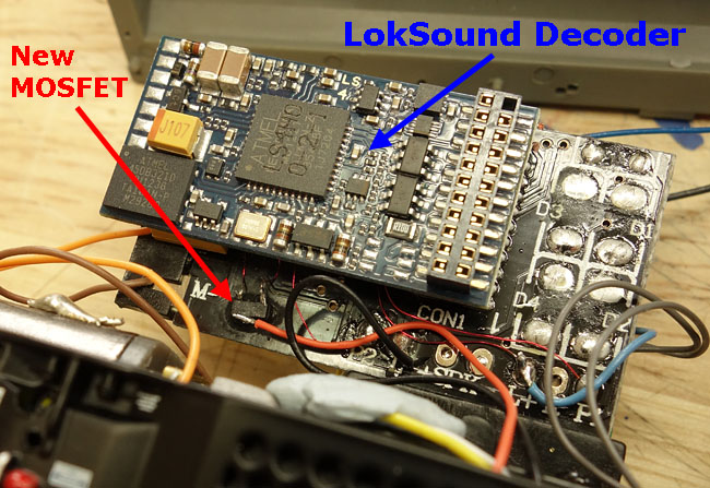
Adding the new MOSFET:
Gate (=Aux 3) and Source (=GND) connections for the 2N7002 MOSFET.
Very thin enamel covered wire links have been soldered to the GND and Aux 3 points indicated in the photo above. These were then connected to a 2N7002 N-channel MOSFET, glued upside-down to the PCB near the motor connections. Finally, the MOSFET drain is soldered to the warning strobes negative wire, while the strobes positive wire is soldered to a common positive pad on the decoder PCB.
The updated decoder pcb assembly.
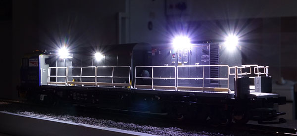
The new LEDs have been fitted to the modules and connected in line with the circuit diagram above, to the original spray module lighting supply (using a small strip board glued to the inside of the water tank module). |
| CV Changes in support of
the hardware mods:
The power car LokSound V4 now requires the Aux 3 function output configuring to provide a double strobe output when button 6 is pressed:
The rear car FL4 now requires that the pink function wire is changed from a double strobe to a constant output, and that this output is triggered from button 5 instead of button 6.
|
 |
 |
|
|
|
First night photos of the power car.
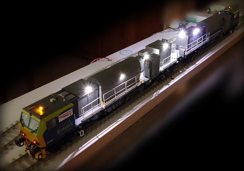
Rear Car
The complete MPV
You've read the book! now check out the movie:
For a You Tube clip of the updated mpv, click here
| Supplier website links: These will be added as the project progresses........
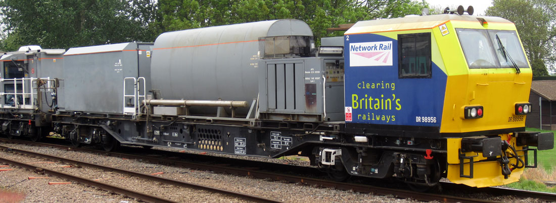
The photos of the real unit were taken at Ely in May 2013. The model photos were taken on the kitchen worktop. |