How to control Hornby Negative Ground lighting modules directly from an NMRA compliant DCC decoder:
Adding a DCC decoder is easy if no functionality changes are required:
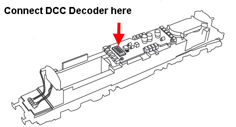
If it is simply required to fit a DCC decoder to a DCC ready Hornby Loco, equipped with a DCC connector, without making any changes in the available functionality, then the decoder can simply be plugged into the DCC socket, without any concerns about negative or positive ground.
More ambitious DCC upgrades to Hornby locomotives, where changes are required to the operation of the lights:
In most of my update projects, I want to at least bring all lighting adjustments under DCC control (replacing the mechanical switch sometimes found on the loco underside) and I usually want to add additional lights. In this situation, I need to be able to combine my new DCC decoder & lighting circuitry with the original Hornby electrics safely, in order to achieve the new functionality.
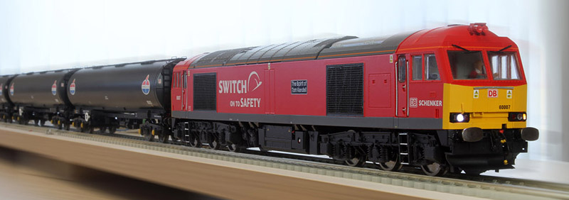
Hornby Class 60 equipped with a Zimo sound decoder.
The problem:
Many of Hornby's earlier DCC ready Diesel locomotive designs (BUT NOT locos Sound equipped from new) incorporate a circuit, in which the wiring to the lighting LEDs uses a negative common connection.... often referred to as "negative ground". The bulk of the circuit is normally housed on a large main, centrally located PCB, while the lighting LEDs are usually located on smaller dedicated lighting PCBs at each end of the locomotive. In a negative ground installation, the positive connections to the LEDs are made via separate wires from the main PCB, while all the negative LED connections are combined together on the lighting PCB, with a single common negative wire connecting the lighting PCB back to the main board.
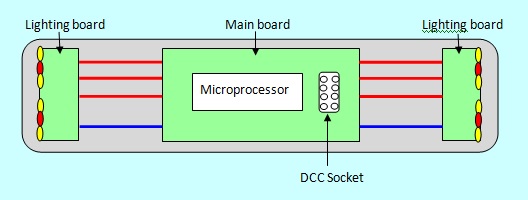 Hornby Loco Block Diagram |
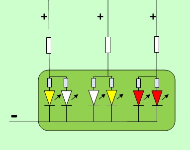 Typical Hornby negative ground lighting board circuit |
However, the internationally agreed standard for DCC decoder function outputs, specifies the use of a common positive connection. The individual control of each function output is provided via individual negative connections. This creates a fundamental incompatibility between the problem Hornby circuits and all NMRA compliant DCC decoders! It is therefore not usually possible to control the original Hornby lighting boards directly from a DCC decoder.

Note: Hornby locos sold with ready fitted sound systems, seem to employ a different main PCB which incorporates a 21 pin DCC connector and their lighting PCBs generally have common positive connections (positive ground) to make them immediately compatible with the DCC sound decoder.
Solutions:
My modified locomotives will only ever operate on a DCC controlled layout. I therefore do not need to maintain an analogue (12V DC) capability. For my projects, the Hornby control circuitry is not required at all. My DCC decoder will completely replace it! However, the connections between the motor and the wheel pick-ups and the 8 pin DCC socket are often very convenient. I therefore normally completely remove the Hornby circuit components from the main PCB, except for the 8 pin DCC socket. The wiring between the main board and the lighting PCBs is disconnected from the main board, but the motor and wheel contact wiring is normally left in place.
This leaves me with a set of lighting PCBs that Hornby will have made, using a common negative electrical connection. In order to drive these LEDs from the DCC decoder, I have two primary options:
Option 1 is to reverse the LED connections on the lighting PCB (de-soldering, then turning the LEDs through 180 degrees and re-soldering.)
Option 2 is to add some simple interfacing circuitry between the decoder outputs and the Hornby negative ground lighting PCB assembly connections.
The LEDs in most modern Locomotives are now surface mount chip types. Great care is needed to remove and refit these devices. The LEDs are often "buried" within a mechanical assembly, which has to be dismantled, to reach them. There is usually a considerable risk of creating a lot more work to rectify collateral damage caused in this process. For this reason I usually opt for option 2!
Interface Circuits:
In order to safely drive the Hornby lighting board (with its negative ground circuit) from a DCC decoder (which has a common positive output) an inverter circuit is needed for each hardware function. This can be done in a number of ways, but I generally use a PNP transistor, as shown in the diagram below:
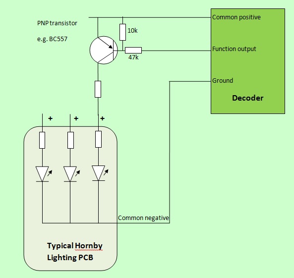 Showing a single function output where the decoder ground is made available. |
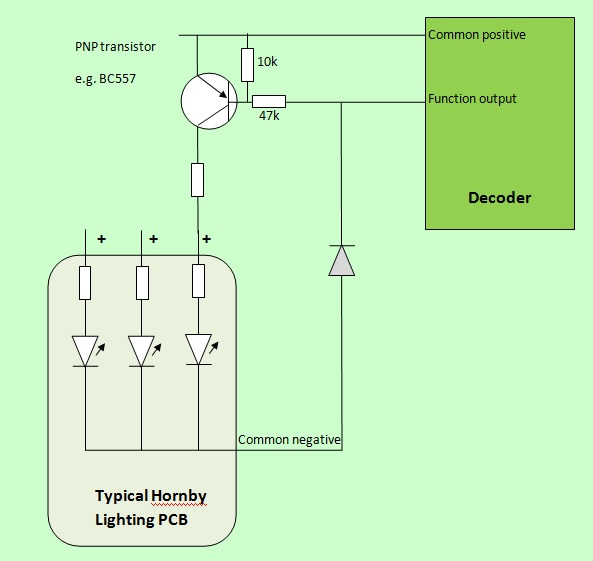 Showing how a diode can provide the negative connection when no decoder ground is available. |
The transistor circuit has to be duplicated between each decoder function output and the corresponding positive connection to the Hornby lighting board.
The decoder function output is either an open circuit or at common positive voltage, when in the off state. This means that the transistor base is at the same voltage as its emitter. In this condition, the transistor remains off, with a very high resistance between emitter and collector and no current flows through the LED (which is therefore off).
When the decoder function output is activated, the output voltage goes negative, becoming similar to the decoder ground voltage. This switches the transistor on and current flows through the LED, turning it on.

Showing three PNP transistor circuits fixed to the rear of each Class 60 cab bulkhead.
(No spring fingers on this 60 variant, these modules will be hard wired to the decoder connections.)
(The ground wire is yet to be soldered in place.)
Main Board Modifications:
 Original Class 60 Main Board. |
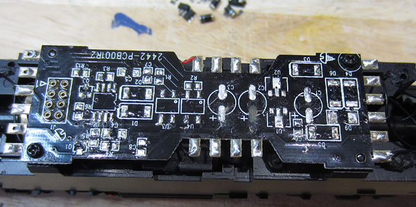 After removal of all parts except the decoder socket. |

Exposed tracks covered with insulating tape.
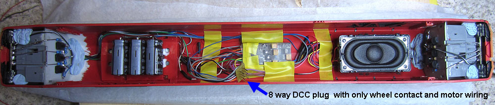
Meanwhile, all the Zimo decoder and lighting circuitry is housed in the upper body shell, with just a flying lead 8 pin DCC plug to connect to the main board for wheel contacts and motor connections.
Typical Complete Locomotive circuit diagram:
Taking the issue a stage further, the PNP interface transistors can also form part of a strategy to achieve the required functionality with a limited number of available decoder function outputs. My other DBS Class 60 has a Bif LokSound V4 decoder with far fewer function outputs than the Zimo, but it has more transistors than it really needs! After a bit more project experience, I've come up with an alternative circuit solution, which I'll retrofit when I get a suitable opportunity...... this is it:
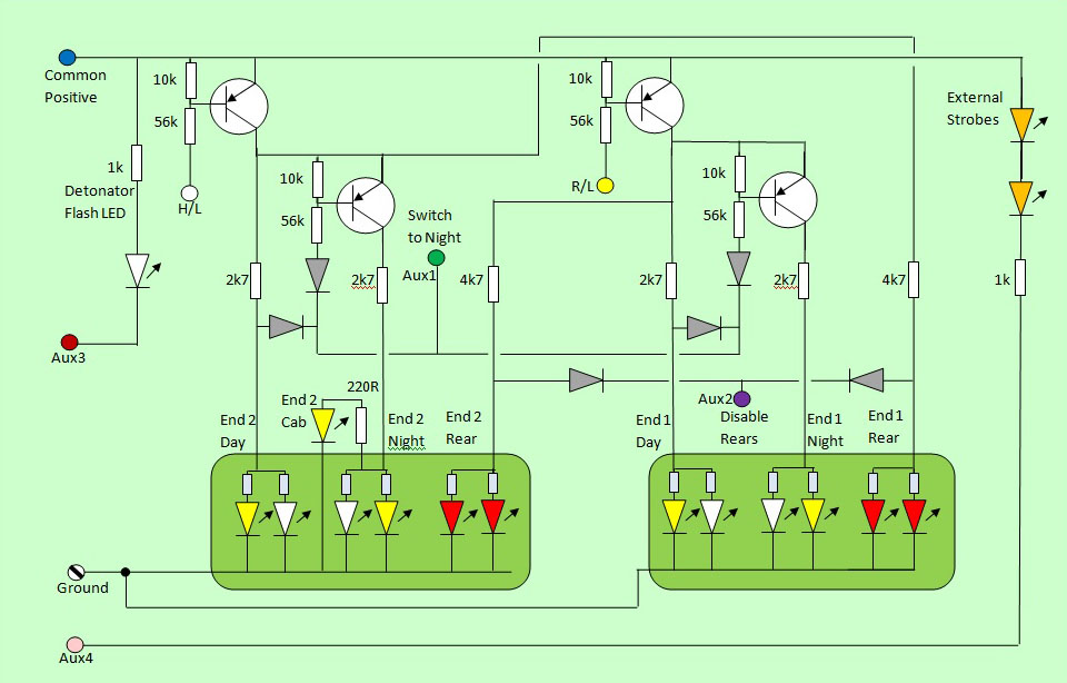
The new Class 60 LokSound V4 circuit
|
|
In
the arrangement above, two PNP transistors provide directional
control of all the running lights on the Hornby lighting boards.
These are controlled by the decoder headlight and rear light
function outputs. The lower pair of PNP transistors are both controlled by the Aux 1 output and switch over to the night running lights when Aux 1 is activated. The rear light disable operation is activated by the Aux 2 output, which when on, forward biases the two diodes connected to it, which starve the active rear lights of voltage, effectively switching them off. Outputs Aux 3 and Aux 4 control new LEDs which are electrically independent of the original Hornby lighting PCBs, so do not require any special interfacing.
Note: The resistors fitted on the Hornby Class 60 lighting PCBs are small value parts (a mix of 33 ohm and 100 ohm.) They are there to balance the current between the two LEDs in each pair, but an additional external higher value series resistor is required to set up the correct total current for each pair. This approach is quite common on Hornby lighting PCBs and it is essential to fit an appropriate additional external series resistor, before powering up the LEDs. |
Just updated the loco (21/05/15) and it all works just as planned!
Less exotic circuit used on my Zimo Class 60s (including more comprehensive lighting).
I've taken a more conventional route to the interfacing on my Zimo equipped Class 60 locos, with 3 PNP transistors interfacing to the lighting boards at each end. A recent thread on the RMweb forum, included some useful info from Class 60 drivers, explaining in some detail how they use the loco lights in different situations:
It seems that headlights are never switched on when operating in the yard. Instead "yard mode" lighting is used (both front markers, but no headlights). Class 60 locos are occasionally used as "super-shunters" and when undertaking this task, rear lights and both front marker lights are used simultaneously at both ends of the loco. Finally, when in normal operation outside the yard, the day or night headlight is used, combined with the marker light on the opposite side. However, if the loco has to stop, and the driver places his master switch in the neutral position, this automatically switches the headlight off but leaves the marker light on. When the loco is about to move, shifting the master switch back to the forward position automatically re-activates the headlight.
When hauling a train, no lights are used at the train end of the loco. Finally, I have witnessed class 57 locos parked, light engine, in a station bay platform, with red rear lights illuminated at both ends. So I'm assuming the Class 60 can also do this if required.
The circuit below is fitted to both of my Zimo equipped 60s and can reproduce all of the above lighting effects, including automatic shut down of the headlights when the locomotive stops and automatic switch on when the loco begins to move.
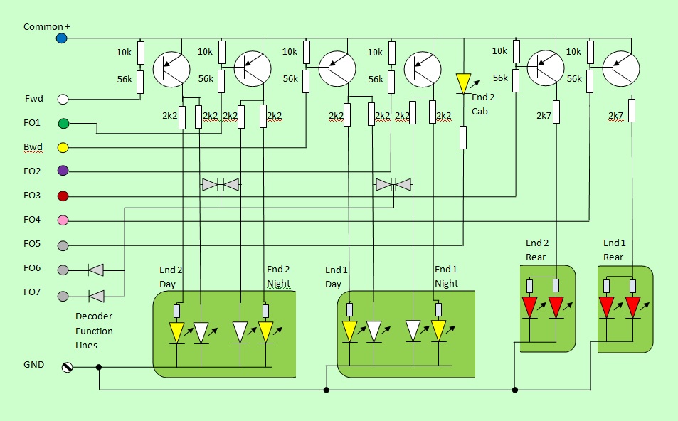
The driver is in the number 2 end cab, which is always at the front when coupled to a train. (Tension lock coupler is at number one end only.)
The diodes are activated by FO6 or FO7 and limit the voltage available to the headlight LEDs to a value that is too low for them to emit light.
FO6 is used to continuously hold off all headlights in yard and super-shunter modes, while FO7 uses a Zimo facility that only activates the
output when the loco is stationary and this can be used to switch headlights automatically, simulating the driver operating his master switch.
(In use from Oct-November 2015, using Zimo V34.10 firmware as all 13 Swiss mapping groups are needed for all FO combinations.)
For more details, please see the the dedicated webpages.
