|
|
DCC conversion and Lighting update of the Bachmann Class 158 2 car DMU. |
|
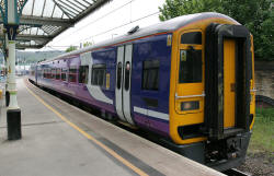
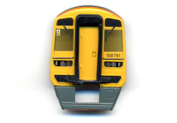
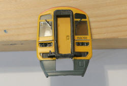
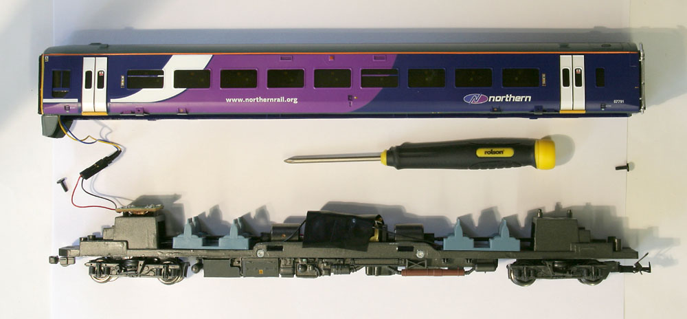
Introduction: This webpage provides a summary of the process adopted to incorporate DCC decoders and correctly operating external LED lighting in the Northern Rail variant of the Bachmann 2-car Class 158 unit (OO gauge). Note that the smaller pictures can be enlarged by clicking on the image. |
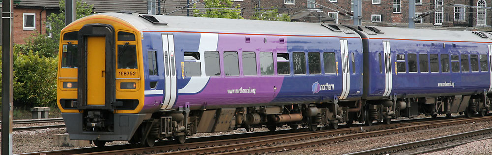
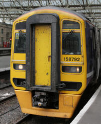
| DCC Conversion Approach: The plan is to use a 4 function and back emf motor controller TCS T4X decoder in the power car and a 4 function TCS FL4 (function only) decoder in the trailer car. To provide correct operation of day and night running lights, 3 function outputs are required, leaving an output available in each car in case I decide to add internal lighting or working platform side lights in the future. External Lighting Modifications: The original lighting fit in the Bachmann model is a bit of a disaster: The LEDs are rounded and should have a flat face. The headlights are yellow and should be white. Both headlights come on together at the forward end of the train, when in the real world, the right headlamp is used only for day running and the left headlamp is used only for night running. No marker lights are provided. (In real Northern Rail 158s, small rectangular yellow tinted white lights are fitted outboard of the headlights in each light cluster.) During day running, the right hand headlight and the left hand marker light are used in the forward car. During night running, the left headlamp and right marker light in the forward car are used. It is planned to add the missing marker lights, replace the existing LEDs with new flat front types (including white types for the headlights) and to arrange for the DCC decoder programming to handle correct day and night running of the lights via function buttons 0 and 1 respectively. |
|
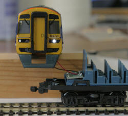
Day running Lights |
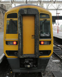
Rear Lights |
| More recent new technology
lights in Class 158 DMUs: A few Class 158 DMUs have now been fitted with a new lighting set, that includes in the original rear light positions, dual function LED technology lights that replace both the original rear lights and the marker lights. The new lights provide a pure white forward marker light or a red rear light function from the same light fitting. The headlights of converted units are normally also upgraded to provide a more efficient and brighter white light source. A supplement to this webpage that describes a way to model the new lighting types can be found by clicking on the "New Lights 158 Page" link below. A further 158 development adds sound and additional lighting.... Click on the "Sound Fitted 158 Page link below to pick up the ongoing story: |
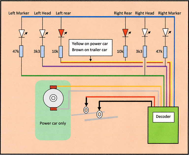
| Circuit Diagram for
lighting and power car connections:
The resistors control the current flowing through each LED. This determines the intensity of the light generated by the LED. The values were established by experiment, for the LED types employed. Some adjustment may be required if different LED types are used. |
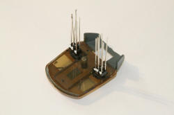
| Achieving Access to the
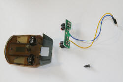
trailer car: First the upper body shell must be separated from the wheeled chassis unit. The two screws in the chassis unit near either end of the car must first be removed. Next the lower edges of the sides are gently eased outwards to release the 4 plastic clips near the centre of the car, allowing the two assemblies to be eased apart. The electrical connector in the wiring between the two assemblies can then be separated. (The flying lead connector wires are removed from the PCB in the chassis unit as it is planned to directly solder the decoder leads to this PCB.) |
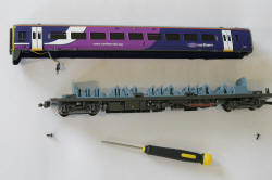
| Access to the Lighting PCB
Assembly: Bachmann have contrived to make the removal of the LED lighting PCB assembly, a real problem, by screwing this to the car front piece, before gluing upper body shell parts of the car together. To remove the original lights, disassembly of the car in one form or another is required. On the example I have, the bonding of the car front piece to the sides and roof was sufficiently weak to allow separation of the front-piece from the rest of the unit with virtually no collateral damage. (However I am advised that this is not always the situation, so other strategies will be required on some 158 units!) The screw holding the lighting PCB to the car front-piece is then removed and the LEDs plus PCB are carefully withdrawn from the front-piece. |
 Lighting PCB trapped between car front-piece and central wall
|
 Car front-piece carefully broken away from sides and roof
|
 Lighting PCB screwed to car-front piece |
 PCB assembly unscrewed and removed from car front-piece |
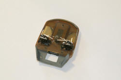
| Fitting the new LEDs: The replacement LEDs are 2mm tower types available from specialist suppliers such as DCC Supplies and/or Bromsgrove Models (see end of article for website links). A 2mm twist drill was run through the original holes to ensure a good fit. The marker lights are also to be made using 2mm tower LEDs. However the real marker lights take the form of a vertical rectangle, so it is intended to drill a 2mm hole from the rear of the front piece, til the drill just breaks through. Then open up a rectangular aperture in the remaining plastic surface. The new LEDs should be a tight fit and when wired together with their resistors, will be robust enough not to require a PCB. |
Modified car front-piece
| Eliminating "Light bleed"
between the new LEDs: Light from the LEDs will couple into adjacent devices if fitted straight out of the bag, producing a very unrealistic effect. To prevent this, the LEDs are painted with gloss black modelling enamel, leaving just the outer face of the 2mm diameter tower exposed. I now also paint a white dot on the negative side of the LED body (shortest lead) before use, to avoid later wiring errors. Once the LED leads are trimmed, its easy to forget the polarity! |
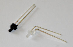
Black painted LED beside "as delivered"
| Fitting LEDs to
front-piece: The headlight and rear light tower LEDs are pressed home until their front face is flush with the front-piece surface. The marker lights are pressed as far into their holes as they will go. The common anodes of each light cluster are soldered together and the other leads are trimmed and formed ready to mount the resistors. |
 LEDs flush mounted |
 The two LED clusters viewed from the rear |
 After lead forming/trimming |
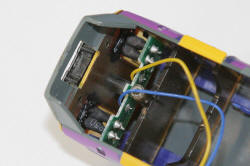
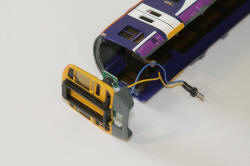
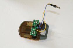
| Adding current control resistors: The resistors (as shown in the circuit diagram above) are mounted in the form of a classic "rat's nest", taking great care to avoid short circuits. The circuitry is kept hidden from direct view through the driver's windows. Attachment points are built in for the decoder cables. |
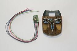
FL4 Decoder beside the completed front piece assembly
| Connect the FL4 decoder: Connect the appropriate decoder wires (as shown in the circuit diagram) to the front-piece assembly. Slide the decoder above the front wall in the upper body shell and along the underside of the roof. Offer up the front-piece to the upper body shell and tape in position. Attach the decoder to the roof underside with an adhesive foam pad. Connect the red and black decoder wires to the small PCB on the lower chassis unit. Use the PCB track pads which already terminate the chassis wheel contact red and black wires. (The 470 ohm resistors mounted on the small PCB are no longer used but can be left in place). Then place the chassis unit on a test track to programme the decoder and test the lighting operation under DCC function button control. |
Decoder fitted to foam pad in the body shell roof
| Programming the CVs: Using the DCC controller (mine is a Bachmann Dynamis) the trailer car FL4 CV values were programmed into the decoder.
The "rule 17" dimming option provided in the TCS decoders has been used, so that when the train is stationary, the headlights and marker lights are dimmed. As soon as the train is made to move, these lights come up to their normal intensity. |
||||||||||||||||||||||||||||||||||||||||||||||||||||||||||||||||||||||||
| Testing the Lights: Button 0 should activate the day running lights (right hand headlight with left hand marker light in the forward direction for this car and both rear lights in reverse). Button 1 should activate the night running lights (left hand headlight with right hand marker light in the forward direction for this car and both rear lights in reverse). |
|
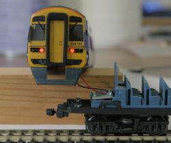
Day running lights are OK (button 0) |
Night running lights are OK (button 1) |
Rear lights work OK (buttons 0 and 1) |
| Completing the trailer car
assembly: Now that correct operation is confirmed, the decoder wires can be tidied and taped to the underside of the roof and the front-piece can be glued back to the upper body shell. The upper body shell can finally be clipped and then screwed to the chassis unit. This completes the trailer car modifications. |
| Modification of the power
car: The power car lighting modifications are carried out exactly as described above for the trailer car. However, the metal chassis of the power car presents an additional risk of short circuits at the rear of the LED and resistor circuitry, so it is important to maintain sufficient clearance from the chassis during construction. First the two retaining screws are removed and upper body shell is separated from the metal chassis unit. |
|
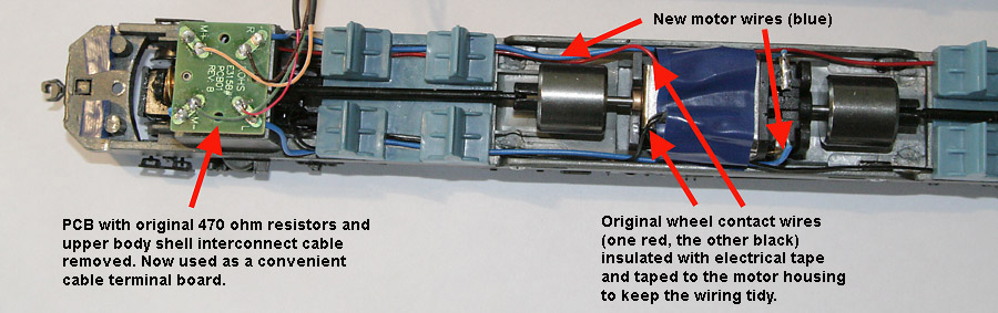
The additional
modifications to the power car concern the motor wiring, which must
be changed for DCC operation.
Remove all the small capacitors and inductors from the motor contact area. The black and red wires connecting to the wheel contacts on each bogie must then have any exposed conductor insulated using electrical tape. The small PCB mounted above the forward bogie can be cleared to provide a convenient wiring terminal. Carefully detach the PCB from its mounting lugs and remove the pair of 470 ohm resistors. Also detach the cable assembly to the upper body shell from the PCB. Fit two new wires to connect each of the motor contacts to the two empty pads on the PCB. Also ensure that the original red and black wheel contact wires are securely connected to the remaining two pads on the PCB. |
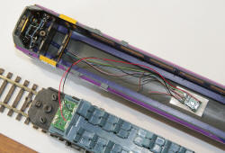
| Mounting the power car
decoder: The larger power car decoder is mounted in the same manner as the trailer car decoder, fitted to an adhesive foam pad in the roof of the upper body shell. The decoder red and black track pick-up wires and the decoder orange and grey motor leads, are then soldered to the appropriate pads of the chassis PCB. The chassis unit is then placed on the test track for programming (see the power car CVs in the above table). After an operational test, the decoder wires are tidied by taping them to the upper body shell roof. The length of the wires between the decoder and the chassis PCB may need adjustment to minimise the appearance of the cables through the side windows, when the upper body shell is re-attached to the chassis unit. |
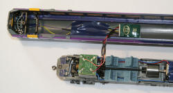
Decoder wiring tidied out of sight of the side windows
| Completing the power car
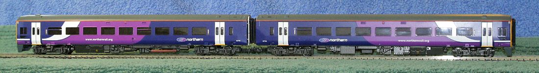
assembly: With correct operation confirmed, and the decoder wires tidied and taped as required, the front-piece can be glued back to the upper body shell. Finally, the upper body shell can be clipped and then screwed to the chassis unit. This completes the power car modifications. When the desired train address has been chosen, programme the same address individually to each car on the test track. Then place both cars on the maintrack, couple up and verify that operation is as expected. |
| Remaining issues: The intensity of the rear lights is a bit on the high side. This is resolved by reprogramming, using the TCS decoder 50% brightness option on the trailer car brown wire (CV53 to 12) and the power car yellow wire (CV50 to 28). The outside dummy couplers fitted to the Bachmann model look nothing like the real BSI couplers fitted to real Class 158 units. This is remedied by some plasti-card modelling to produce replacement dummy BSI couplers. |
| Supplier website links:
The photos of real class 158s were taken during our recent holiday in the Lake District, where we took a day out from walking, to travel on the ex-Midland Railway Settle to Carlisle railway line (actually Penrith to Carlisle, then Carlisle to Skipton and return). The photos of the model were taken hand held on the kitchen worktop at 1600 ISO with fill-in flash. |