Supplementary Page covering New light fittings now found on some Class 158 DMUs.

|
Supplementary Page covering New light fittings now found on some Class 158 DMUs. |
|
|
Introduction: The availability of new full size light emitting diode technology dual function marker and rear light units has resulted in many Class 158 DMUs receiving mid-life lighting updates. This webpage shows the difference in the lighting arrangements and documents the update of a second Bachmann Class 158 pair, with this type of lighting. Note that the smaller pictures can be enlarged by clicking on the image. |
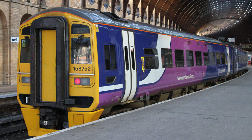
Northern Rail Class 158 at York, fitted with new LED marker / rear Lights
| The Modified Lighting
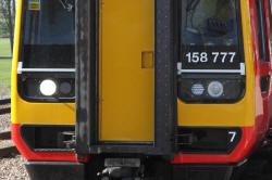
Assembly: The photos below show refurbished East Midlands Class 158 Two car DMUs at Ely station in Cambridgeshire during April 2010. The original rear lights have been replaced with new dual function LED technology lighting units. The original marker lights (vertically orientated rectangular lights in the outboard position of the light clusters) are not included in the new light housings. At the forward end, during day running, the right headlamp is used with the left marker light only. During night running, the left headlamp is used with the right marker light only. At the rear end of the train, both rear lights are used simultaneously in both day and night running. |
|
Day running Lights
|
Rear Lights
|
|
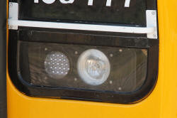
Close-up of light housings |
Driver side light cluster |
| Modelling a dual function
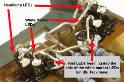
white/red LED lamp: The white light produced by the new lamps, when in front marker light mode, is pure white. The only currently available potentially suitable dual function white/red LED that I am aware of is a 2mm tower LED produced by DCC Concepts (Australia) and sold in the UK by Bromsgrove models. However, this LED exhibits a yellow tinted white light which is quite unlike the real thing. DCC Concepts have just released a micro-miniature pre-wired pure-white/red chip-LED (about half the size of a 0603 SMD LED) in Australia. I believe this device could be successfully used for this application, with a suitable lens fitted in front of the LED. Unfortunately at time of writing, this device is not yet available in the UK from DCCC's normal UK source at Bromsgrove. [Note as of December 2009, although the pre-wired dual white/red chip "nano" LEDs are now available from Bromsgrove Models, the examples I obtained consist of back to back red and white chip LEDs i.e. the red LED points at 180 degrees to the white LED...... so NOT in fact useful for this application.] An expedient solution has been prototyped, using a pure white tower LED to be fitted in the new light position. This has a red tower LED beaming at right angles into the white LED body at the base of the tower. The bodies of the two LEDs are painted white to assist internal light reflections, then when this coat has dried, a coat of black paint is applied to cut down unwanted light leakage. (The paint is kept away from the wanted light paths of course).
A very small current is needed to produce the right order of light from the white LED as a front marker light, while near maximum light output is required from the red LED to achieve a bright enough rear light function. While a fairly crude approach to the problem, the prototype looks sufficiently promising to try on a Bachmann Class 158 unit, where fortunately there is room to accommodate a two LED solution of this type, with shortened LED towers. If the arrangement is not successful, it will be retrofitted with the new DCCC chip LED when this becomes available. |
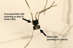 Prototype LED pair |
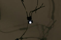 White LED active |
 Red LED active |
(The camera exposure is reduced to keep the light source out of saturation)
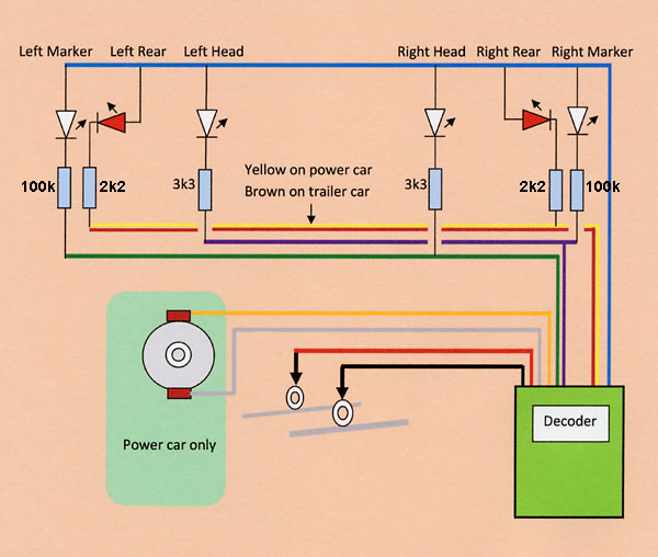
| Circuit Diagram for
lighting and motor connections:
The resistors control the current flowing through each LED. This determines the intensity of the light generated by the LED. The values were established by experiment, for the LED types employed. Some adjustment may be required if different LED types are used or different light levels are required. |
| Preparing the LEDs for the
power car: The tower of the white LEDs of the dual LED installation is reduced in length, so that the LED body just touches the rear face of the loco front piece when the front face of the tower is a flush fit. (First cut slightly long, using a Stanley knife, then carefully file to final size using a fine flat needle file.) The red LEDs receive similar treatment, leaving an even smaller amount of the tower protruding from the LED body. This is necessary to allow the LEDs to be mounted on the available space at the rear of the loco front piece. The dual LED components are coated with white paint (except for the front faces and the side window in the white LEDs). When this has dried, the white areas are over-painted with opaque black paint. The headlight LEDs receive only a coat of black paint (to minimise unwanted light leakage). A blob of white paint is placed on the body of each LED adjacent to the negative (shorter) lead. (To identify polarity after the leads are trimmed.) |
| Fitting the LEDs to the
power car: The two headlight LEDs and the white dual light parts are inserted into the 2mm holes in the loco front piece until the LED front faces are flush with the front face of the loco. The red LEDs are mounted on a small Blu Tack pad, with their tower ends pressed hard against the windows in the white LED paintwork. The LEDs are all orientated so that their positive leads are adjacent to the bottom of the front piece. The positive leads of all six LEDs are soldered together to provide mutual support. The series resistors are soldered to the negative end of the LEDs and physically located between the front windows, to hide them from view. The other aspects of the conversion can be seen in the original Class 158 webpage at (click here). |
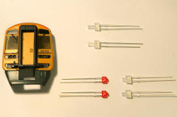 LEDs with towers trimmed to fit before painting
|
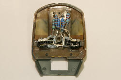 The LEDs fitted to the end wall of the car
|
 Front view with LEDs in place
|
 Close-up of the tower LEDs including the dual light assembly
|
|
Problems and fixes: The red LED light leakage when the rear lights are on was excessive and would have shown through the cab windows. This is now controlled by adding small amounts of Blu Tack over the main point of escaping red light, at the junction of the white marker and red rear lights. The good news is that the dual colour light concept works well! |
| CV Programming:
The "rule 17" dimming option provided in the TCS decoders has been used, so that when the train is stationary, the headlights and marker lights are dimmed. As soon as the train is made to move, these lights come up to their normal intensity. |
||||||||||||||||||||||||||||||||||||||||||||||||||||||||||||||||||||||||
| Testing the Lights,
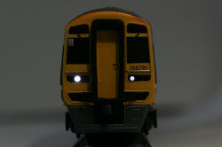
initially on the power car: Button 0 activates the day running lights (right hand headlight with left hand marker light in the forward direction and both rear lights in the reverse direction). Button 1 activates the night running lights (left hand headlight with right hand marker light in the forward direction and both rear lights in the forward direction). |
|
Day running lights (button 0, forward)
|
Night running lights (button 1, forward)
|
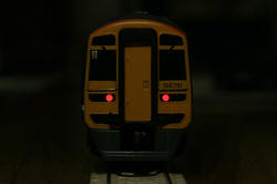
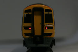
Rear lights (buttons 0 or 1, reverse) (Darker image to show actual light colour) |
| Modification of the trailer
car: The trailer car lighting fit is very similar to that of the power car. However, the plastic chassis and lack of bogie gear boxes gives more freedom in the placement of the series resistors. |
| Testing the Lights,
on the trailer car: Button 0 activates the day running lights (right hand headlight with left hand marker light in the reverse direction for this rear car and both rear lights in the forward direction). Button 1 activates the night running lights (left hand headlight with right hand marker light in the reverse direction for this rear car and both rear lights in the forward direction). |
|
Day running lights (button 0, reverse) |
Night running lights (button 1, reverse) |
Rear lights (buttons 0 or 1, forward) |
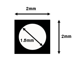
| Problems and fixes: The marker lights look a little too big compared to the photos of the real locos, but making a neat size reduction by painting around the periphery of the lights proved beyond my painting skills. Worth trying to produce the hexagon pattern of the original with a paint brush, if your painting skills are up to it! Plan B: Make a tiny blanking plate: A 2mm x 2mm very thin plasti-card square with a 1.5mm hole in the centre. Paint Satin black on the outside and place over the marker/rear light. Secure with super-glue.
This worked well on the trailer car, where the marker/rear lights were slightly sub-flush. However on the power car the LED face was slightly protruding and the fit was unacceptable. However the rear lights are the most obvious in terms of being oversize when compared to the real loco and the normal operating direction of the model will result in the rear lights displaying on in the trailer car, so I'll live with the slight discrepancy between the cars. |
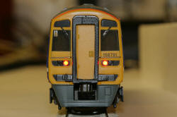
 Headlight and marker light operation (with blanking plate) |
Rear light operation (with blanking plate) |
| Operation of the complete
train: Lights operate as planned, however in order to get reliable starting at minimum speed, I had to move CV3 (acceleration delay) up to above 20 (40 gave acceptable results). I was careless enough to have a shorting accident with the black/white decoder wire touching the track after initial programming. The Dynamis trip operated and I thought I'd been lucky..... so this problem maybe related to self induced decoder damage? As operation seems otherwise unaffected, I'll keep my fingers crossed and live with the unusual setting. |
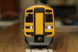
Below: The finished new tech lights Northern Class 158:

Northern 158 heading our way
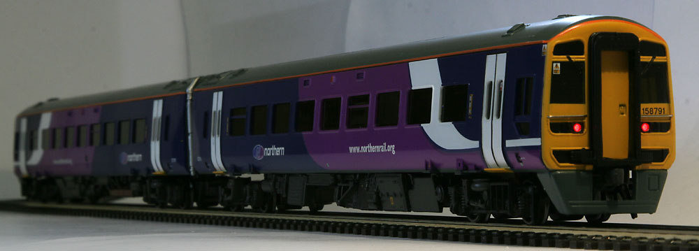
Northern 158 heading away into the dusk
Below, the real thing:
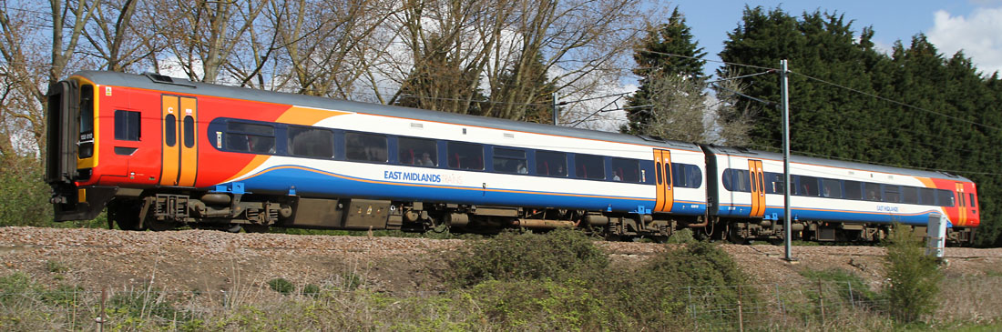
Refurbished East Midlands Class 158 with the new lighting fit, approaching Ely station
| Supplier website links:
The photos of real East Midlands Class 158s were taken at Ely during April 2010. The Northern Rail Class 158 was photographed earlier, at York. The photos of the model were taken on the kitchen worktop at 200 ISO, using a tripod. |