|
DCC Lights and sound update for
the Hornby Network Rail New Measurement Train Class 43 HST Power car and Trailer Car
|
|
|
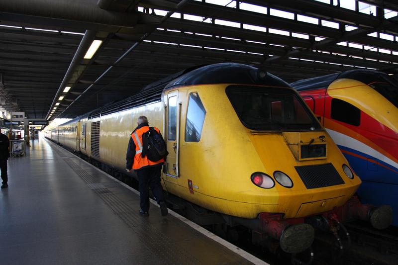
Introduction: The Network Rail New Measurement HST power car pack was a bargain impulse buy. However, quite a bit of work will be required to get the full train into shape. In this page, I start with updates to the power cars to sort out the lights and to add a DCC sound system. |
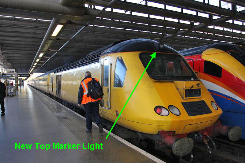
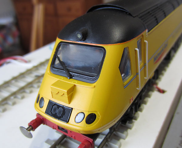
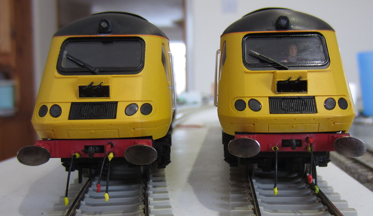
| New Top Marker Lights: Before designing the overall lighting circuit, an obvious addition required is a top marker light for each power car:
The upper marker lights were added fairly recently and are not reproduced in Hornby's model.
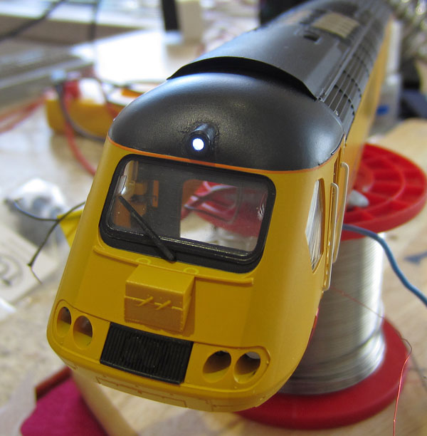
My solution is formed using thin plasticard to produce the housing, with a short 1.5mm diameter optical fibre forming the lens. The housing is super-glued to the cab roof, with the fibre passing through a hole drilled through the roof.
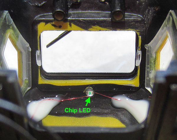
Looking down into the inside of the inverted cab roof. (The wire retaining glue has not dried yet.)
Illumination is provided by a daylight white chip LED, superglued to the rear of the fibre. A 22k ohm series resistor produces about the right level of light from a 14 Volt DCC function output. A small disc of Blu Tack was used to cover the rear of the LED assembly, to prevent the cab light illuminating the new lens from behind. |
| Choice of Sound Decoder: The options seem to be LokSound V4 from South West Digital, Digitrains or from Olivias Trains......... Nothing found so far on Zimo. I've decided upon the Olivias Trains ESU LokSound V4 solution, as already fitted to the Cross Country HST. |
|
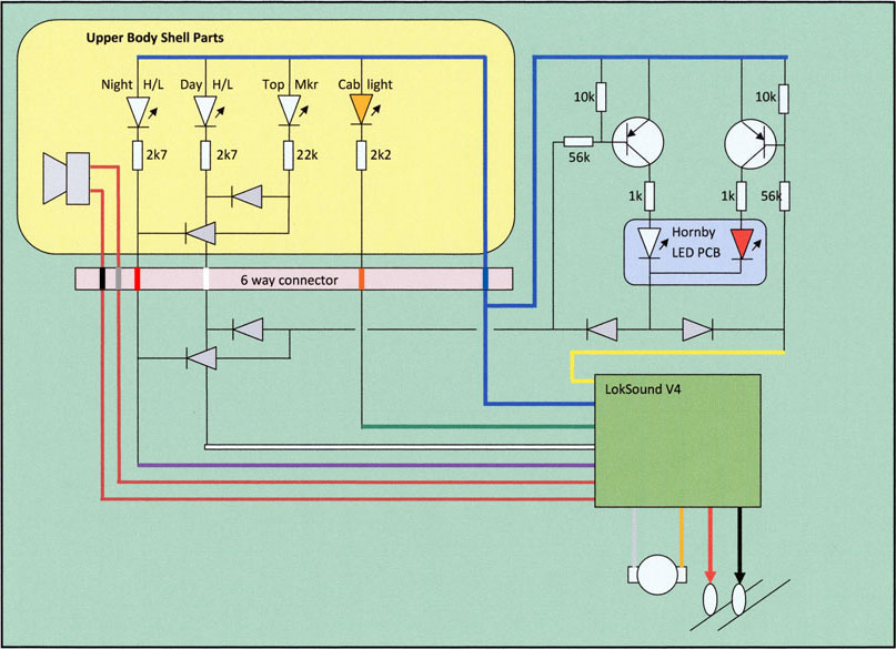
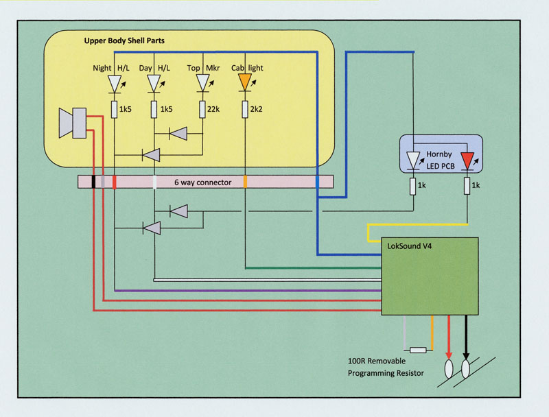
The planned Circuit Diagram:
New white day and night headlights are fitted, overcoming the low intensity of Hornby's original day headlight. The new upper marker light, described above, plus Hornby's cab light are also incorporated. Hornby have used their favourite common negative circuit arrangement for the original LED PCB assembly. This mechanical assembly is too fragile to risk dismantling for modification to a common positive configuration, so I have used PNP transistors and a few diodes to interface between the LokSound V4 decoder and the original Hornby loco lighting components. I will strip all of the original Hornby components from the main PCB, before constructing the new circuit. The main circuit board will be covered by double sided foam tape, to insulate the new parts from the original tracks and to hold the new parts in place. A multi-way connector will be used to provide the electrical interface between the chassis and the lights wired to the upper body.
|
|
Adding the night headlight and
fixing the intensity of the day headlight:
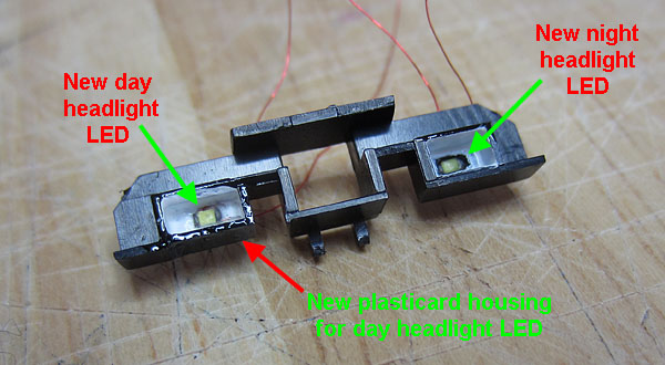
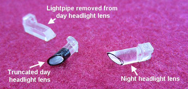
Hornby conveniently provides the night headlight lens. (The Left hand inboard light below the cab windscreen.) The lens terminates in a clear block which is housed within the shroud assembly moulding that supports the rearlight/marker light optics. The night headlight LED is fitted through a hole cut in the rear of the shroud moulding, beaming directly into the rear block of the night headlight lens. To fix the existing day headlight, the lens is separated, near the back of the outer cylinder, from the lossy convoluted light pipe that routes the original LED light into the lens. A new LED is fitted in a plasticard housing built on to the shroud moulding, to beam directly into the rear of the remaining lens. A matt black painted plasticard blanking plate will then be glued on to the shroud immediately in front of the white LED housing to block light from this source. (The original white LED cannot be disabled as it continues to provide the low intensity light required for the lower front marker lights.)
Modified shroud moulding (minus blanking plate at this stage).
Day & Night headlight lenses (I could have left the night lens in place within the upper body)
The technique described above is very similar to that used on the Class 43 First Great Western locos. If you would like to see more photographic detail, use this link to move to that project: FGW Class 43
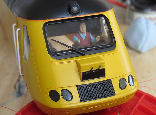
Remembered to glue the new driver in place before re-assembly of the lights and cab. Then painted the camera window gloss black. |
|
Fitting the speaker for the
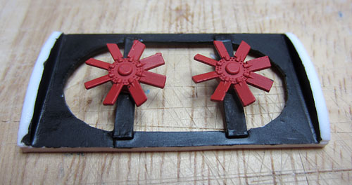
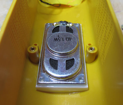
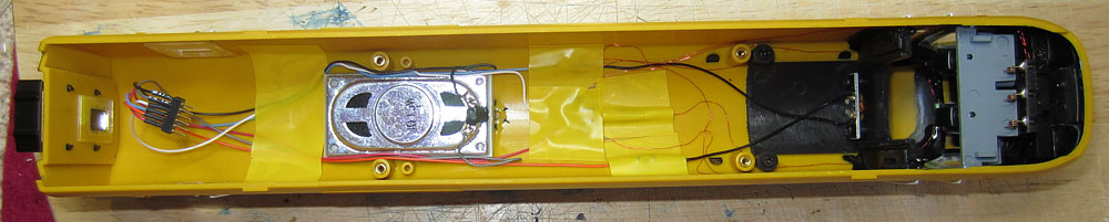
sound system: The Hornby Class 43 locos have few speaker location options as discovered on the earlier Cross Country variant. A similar approach is taken on the NMT power cars to that used on the previous units. The ESU 50334 speaker drive unit is fitted directly below the 2 roof fan vents. A plasticard collar provides an air tight seal and this time, also incorporates the fans previously removed from the rotating fan drive box.
Top view of plasticard speaker collar, with fans mounted and matt black paint on the upper surfaces.
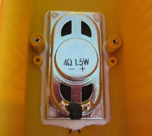
Collar glued to loco roof and speaker glued to the collar underside.
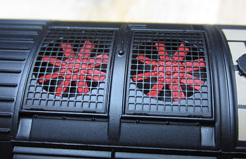
Top view of the roof, showing the fans located in the vent apertures.
Glu 'n Glaze sealing compound providing the air tight seal
The ESU enclosure is not used (insufficient clearance) but there is enough physical isolation provided by the upper body shell to prevent cancellation of the front and back pressure waves. Electrical tape, on the inside of the body shell, is used to seal the adjacent side grill cooling vents. |
|
The main printed circuit board
assembly:
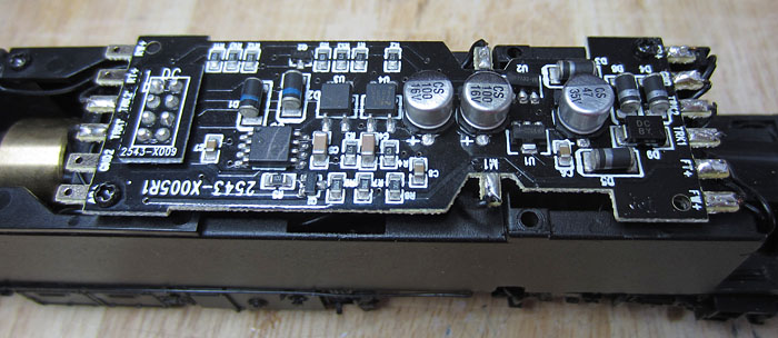
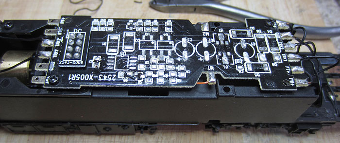
The Hornby circuit used in the power car is an interesting and in my view, completely over the top, solution to the requirement. For DCC only use, in conjunction with the improved headlights now fitted all the main PCB surface mount components are stripped from the board.
Surface mount parts removed, excess solder tidied and wheel contact plus motor wiring trimmed.
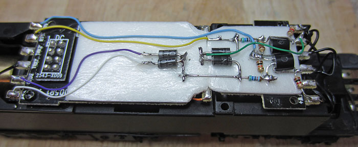
The PCB is retained to provide interconnect between the wheel contacts and the motor, to the decoder, via the 8 pin socket. The unused end tabs are isolated from the rest of the PCB by cutting the tracks. The RF suppression capacitor is removed from the motor contacts. Double sided adhesive foam tape is stuck to the top of the PCB to provide insulation and adhesion to the new parts required to interface the decoder to the lights.
Two PNP transistors & supporting circuitry, required simply because Hornby have used a common negative supply for the original LEDs
|
Local parts taped to the upper body roof pending testing (when confirmed OK, they will be glued in place). 6 way connector also wired in.
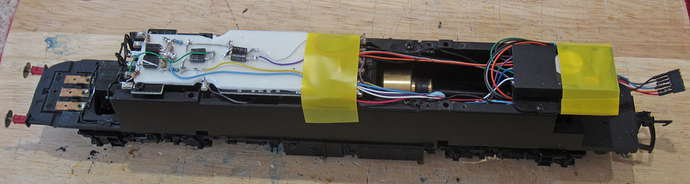
Decoder fitted on the rear platform and wired to the chassis circuit and corresponding 6 way connector.
Wires routed to avoid flywheel & driveshaft and kept low to avoid the speaker above.
|
Making Changes to the LokSound
function mapping to combine lights and sound: Using the details already proven on an earlier MTU powered HST:
Power Car CV Changes:
Power and Trailer Car Sound volume CV Changes:
That all seems to be working well. The sound is pretty good after dropping the engine sound level, to bring up the horns and other peripheral sounds. However, the throttle response on the sound project is quite slow, particularly when powering down for a stop, there is a considerable delay before the engine reverts to idle, but I can live with that on a train that will be on the move most of the time it's being displayed. Some further changes to free up buttons 9 & 12 for coach lighting effects using an FL4 decoder in the track recording car:
|
|
The Trailer Car Circuit Diagram:
New white day and night headlights are fitted, overcoming the low intensity of Hornby's original day headlight. The new upper marker light, described above, plus Hornby's cab light are also incorporated. Hornby have used a positive ground circuit for their own LEDs in the trailer car so all we need are a few diodes to interface between the headlights and the marker lights. I'll re-use what I can of the original Hornby components on the main PCB. A multi-way connector will be used to provide the electrical interface between the chassis and the lights plus speaker, wired to the upper body. The LokSound decoder will only accept programming instructions if a low impedance is connected across the motor terminals. So these wires will be taken to a hidden spot under the chassis, with a 100 ohm resistor ready to be connected during programming operations only.
Trailer Car CV Changes:
Some further changes to free up buttons 9 & 12 for coach lighting effects using an FL4 decoder in the track recording car:
Matching the speed related CVs:
|
|
A few additional problems with
the trailer car: The new top marker light housing was built up in the same way as that used on the power car. However, this time I used gel super glue to bond it to the front of the trailer car, just above the windscreen. The fumes attacked the clear surface of the windscreen, leaving a cloudy finish. I then compounded the problem by trying to polish the surface and in fact made it worse. Next attempt to cheer it up is with clear varnish.
Bad case of condensation on the trailer car windscreen.
While messing up the windscreen I noticed that the windscreen wiper was well away from the screen and after fruitless attempts to bend it back into position, I've glued it back in place with Glu n' Glaze. (Super glue would do a better bonding job, but I wont be using that anywhere near window transparencies any time soon!!!! ). I'll let the varnish add to the bonding forces. The trailer car main PCB was stripped of all parts except the surface mount 1k resistors for the original Hornby LEDs. Two diodes were positioned on appropriate points of the track pattern. The decoder was bonded down to a double sided foam pad fixed to the ballast strip below the main PCB, and connected up to the 6 way connector and appropriate pads on the main PCB in line with the circuit diagram. Finally, when bringing the chassis assembly back together with the upper body shell, the spring contacts at the front of the model proved very unreliable, so I removed the chassis contact tabs and hard wired the spring pads to the corresponding Main PCB solder tabs. (Duplicating two contacts in the 6 way connector, to avoid further complications.)
Condensation varnished out & dangly bits added. (I'll have to re-fix that wiper at the correct angle though.) |
| Button | Action |
| 0 | Day running lights |
| 1 | Power car engine start/stop |
| 2 | Single tone horn (directional, leading car only) |
| 3 | Two tone horn (directional, leading car only) |
| 4 | Brake release air emission |
| 5 | Dispatcher's whistle (directional, rear car only) |
| 6 | Guards door slam (directional, rear car only) |
| 7 | Right Away buzzer |
| 8 | Trailer car engine start/stop |
| 9 | Track recording car track & laser lighting & VDUs |
| 10 | Wheel flange scrape (only when moving) |
| 11 | Night running lights |
| 12 | Pantograph car OHL illumination spots |
| 13 | Rail Clack (only when moving) |
| 14 | Mark 3 coach suspension (only when moving) |
| 15 | Shunt mode |
| 16 | Volume booster |
| 17 | Zero momentum mode |
| 18 | Power car cab light |
| 19 | Trailer Car cab light |
| 20 | Spirax valve popping |
| 21 | Compressor |
Function Mapping summary for the NMT.
| Supplier website links:
The photos of the model were taken using a Canon Ixus 220HS on the kitchen worktop, sometimes with on-board flash. |